


Certain tests used to characterize an output transformer can require more voltage or more power than the typical modern function generator can provide. In his post on determining primary inductance (https://groupdiy.com/index.php?topic=73039.0), CJ mentions increasing voltage level until L stops increasing with it to find the saturation voltage at a particular frequency, for example. A second example: transformer frequency response may look different when the core is fully excited vs when it isn't. So the ability to provide test signals of sufficient voltage or power is key.
Few inexpensive, modern signal/function generators of the type many folks use today are capable of providing more than 7 - 10 volts RMS. Many put out much less. Power output is usually below 125mW (~21dBm). Even most older oscillators output a maximum of 20dBm or less into 600 ohms. For testing output transformers with power ratings of +24dBm and up, this won't cut it.
A signal amp/function generator amp is useful for these situations. If it's not practical/possible to test using the amplifier the transformer will be used in, or if you're just testing a transformer to see what kind of project it might be useful in, you'll need an amp like this. It should not only deliver the voltage/power you need into the load the primary presents (plus whatever series resistance you add) it should have the frequency response needed (at least down to 10Hz IMO, preferably lower) and not add significant distortion to the signal. A DC amplifier will allow you to inject signals well below the audible band, which is useful to accurately characterize the -3dB low freq point at whatever frequency it might be at. But you may or may not need that capability in your particular scenario.
It can be hard to find a good amp for this job. I bought a cheap chinese signal amp and a couple of old DC amps off ebay, but none of them could provide enough clean output to satisfy the requirements. Thought I'd share what I ended up with.
The two solutions that worked well for me were both dirt cheap. One is a DIY solution, the other purchased and modified.
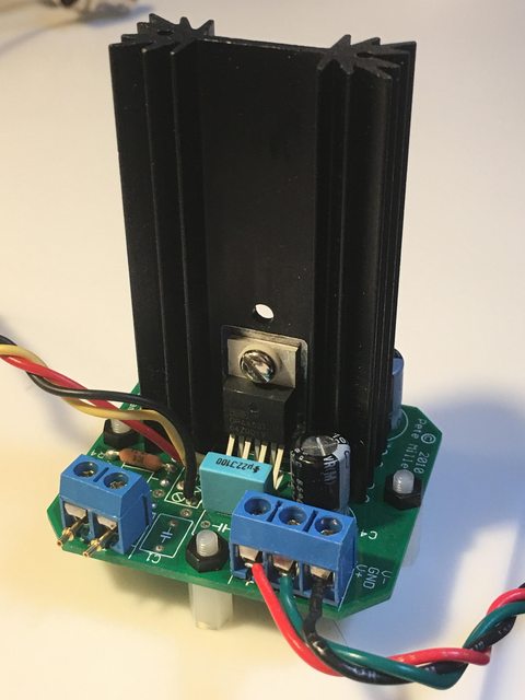
My old buddy Pete Millett sells a power op amp board on eBay that was designed for the OPA452/OPA453 power op amp. He sells a pair for $20. You can also use OPA547 or OPA548 chips if want more power. I used the 453 and it works great for pro audio projects. If you need to test transformers for power amp projects, you'll definitely need to upgrade to a more beefy chip.
Link to the boards:
https://www.ebay.com/itm/DIY-PCB-2x-Power-Opamp-Driver-PCB-OPA452-OPA547/150913782253?hash=item23232991ed:g:OmUAAOxyIPNTcmmE
Description on Pete's website:
http://pmillett.com/pwrop.htm
Super easy to build. Took half an hour to stuff the PCB. You need to supply the power. Pete sells a cheap supply PCB with it, but you'll have to design it yourself using PSUD or similar to determine part values. I ended up designing a +/-36 volt supply with it, and it worked for both this amp and the one below.
Second amp is one I came across on the web after stumbling onto an article about finding/building a signal amp. I ended up buying one from Alibaba like the author did, but later they started becoming available on eBay. I think I paid $35 or so. It's larger than the one above and is based on the OPA541 power amp chip, which is more powerful than the OPA453 (also generates a lot more heat, as you'll see when you read the original article that turned me on to these).
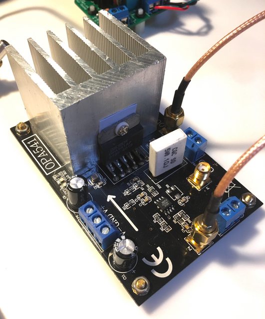
I made the modifications the author of the article below made and I've been happy with the result. It involves swapping out some SMD resistors and removing a cap, IIRC, but I didn't have a problem with it. You could also just use the amp as is if you don't need DC amplification or don't want to set the gain at 10.
https://www.dmcinfo.com/latest-thinking/blog/id/9462/low-cost-function-generator-amplifier-diy
You can find those all over eBay now, and even on Amazon. Be sure they have the chip you want in them, as I see them being sold now with any of several different TI power amp chips.
Simple projects that yielded good solutions to the problem.
Few inexpensive, modern signal/function generators of the type many folks use today are capable of providing more than 7 - 10 volts RMS. Many put out much less. Power output is usually below 125mW (~21dBm). Even most older oscillators output a maximum of 20dBm or less into 600 ohms. For testing output transformers with power ratings of +24dBm and up, this won't cut it.
A signal amp/function generator amp is useful for these situations. If it's not practical/possible to test using the amplifier the transformer will be used in, or if you're just testing a transformer to see what kind of project it might be useful in, you'll need an amp like this. It should not only deliver the voltage/power you need into the load the primary presents (plus whatever series resistance you add) it should have the frequency response needed (at least down to 10Hz IMO, preferably lower) and not add significant distortion to the signal. A DC amplifier will allow you to inject signals well below the audible band, which is useful to accurately characterize the -3dB low freq point at whatever frequency it might be at. But you may or may not need that capability in your particular scenario.
It can be hard to find a good amp for this job. I bought a cheap chinese signal amp and a couple of old DC amps off ebay, but none of them could provide enough clean output to satisfy the requirements. Thought I'd share what I ended up with.
The two solutions that worked well for me were both dirt cheap. One is a DIY solution, the other purchased and modified.
My old buddy Pete Millett sells a power op amp board on eBay that was designed for the OPA452/OPA453 power op amp. He sells a pair for $20. You can also use OPA547 or OPA548 chips if want more power. I used the 453 and it works great for pro audio projects. If you need to test transformers for power amp projects, you'll definitely need to upgrade to a more beefy chip.
Link to the boards:
https://www.ebay.com/itm/DIY-PCB-2x-Power-Opamp-Driver-PCB-OPA452-OPA547/150913782253?hash=item23232991ed:g:OmUAAOxyIPNTcmmE
Description on Pete's website:
http://pmillett.com/pwrop.htm
Super easy to build. Took half an hour to stuff the PCB. You need to supply the power. Pete sells a cheap supply PCB with it, but you'll have to design it yourself using PSUD or similar to determine part values. I ended up designing a +/-36 volt supply with it, and it worked for both this amp and the one below.
Second amp is one I came across on the web after stumbling onto an article about finding/building a signal amp. I ended up buying one from Alibaba like the author did, but later they started becoming available on eBay. I think I paid $35 or so. It's larger than the one above and is based on the OPA541 power amp chip, which is more powerful than the OPA453 (also generates a lot more heat, as you'll see when you read the original article that turned me on to these).
I made the modifications the author of the article below made and I've been happy with the result. It involves swapping out some SMD resistors and removing a cap, IIRC, but I didn't have a problem with it. You could also just use the amp as is if you don't need DC amplification or don't want to set the gain at 10.
https://www.dmcinfo.com/latest-thinking/blog/id/9462/low-cost-function-generator-amplifier-diy
You can find those all over eBay now, and even on Amazon. Be sure they have the chip you want in them, as I see them being sold now with any of several different TI power amp chips.
Simple projects that yielded good solutions to the problem.
 eAAAOSwFx5cB4OH


![Soldering Iron Kit, 120W LED Digital Advanced Solder Iron Soldering Gun kit, 110V Welding Tools, Smart Temperature Control [356℉-932℉], Extra 5pcs Tips, Auto Sleep, Temp Calibration, Orange](https://m.media-amazon.com/images/I/51sFKu9SdeL._SL500_.jpg)


