A precision driver for a Magic Eye?
Why?
How are you going to put 10%, 20%, ...100% marks on the phosphor screen inside the bottle?
This tube: IC2A must pull to the negative rail (LM324) or R116 must be biased a few volts above IC2A's negative rail so that your cathode-drive circuit will force amp-triode to maximum current.
> Would this circuit do ok
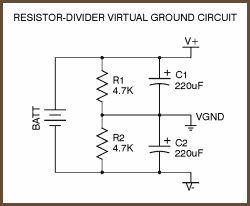
Depends entirely on the parts values not shown on your plan. If impedances are in the GigaOhm zone, then sure, 4K7||4K7 is pretty solid. If C106 is taking 35mA peak pulses, then 220||220uFd will damp that, but not to-zero. If C106 jolts kick the V/2 point around and something amplifies that kick (the path can be subtle; I posted an analysis of the Cmoy headphone amp which shows heavy offset in some cases), results may be unexpected.
Hint: your to-"ground" caps C104 C106 may and probably should return to hard-ground, not V/2. With FET input on IC1A, R101 can be a Meg. Then all other V/2 stuff _appears_ to be opamp inputs or the zero pot. Small or constant loading on the V/2 supply. I do agree that, unless you make a million of these, you may just as well buffer the V/2... another <19 cent amp is cheaper (in coffee and brain-pain) than computing circuit sensitivity and leakage.
I assume the Magic Eye is a short cut-off type. Some made for US AM radios have extended cut-off and won't reach maximum deflection until 30V or so on the first grid.


![Soldering Iron Kit, 120W LED Digital Advanced Solder Iron Soldering Gun kit, 110V Welding Tools, Smart Temperature Control [356℉-932℉], Extra 5pcs Tips, Auto Sleep, Temp Calibration, Orange](https://m.media-amazon.com/images/I/51sFKu9SdeL._SL500_.jpg)


") I used to play with old radios when i was a kid and was specially fascinated by these glowing eyes. So the reason for me to use them now is more aesthetic/emotional but i'd like it to have a decent functionality of course.
I used to play with old radios when i was a kid and was specially fascinated by these glowing eyes. So the reason for me to use them now is more aesthetic/emotional but i'd like it to have a decent functionality of course.