Square wave generator

GroupDIY Audio Forum

Help Support GroupDIY Audio Forum:

This site may earn a commission from merchant affiliate links, including eBay, Amazon, and others.

Moby

www.mobytransformers.com BV.8, Bv.11, Bv.12, T14/1
GDIY Supporter
Joined
Jun 3, 2004
Messages
2,136
Location
Serbia
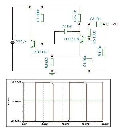
I found this circuit somewhere on the web and it seemed interesting as pocket SQW generator. Simulation shown not perfect square so I wonder is it possible to improve it?
SQUAREGEN.jpg
 
Moby,
you sure love that simulator, the question is, can you give a hand waving explanation of how the circuit works?
I just worry that you seem to be using the sim as an excuse not to really understand the circuits.

Better square wave generators are not hard to design, but parts count will increase and what is there is good enough for a lot of quick line tests and the like. If I was trying for a really good square wave I would probably not start from here, but for the stated purpose this is not bad.  With more voltage available I would probably go for a cmos schmitt trigger based relaxation osc or similar (one resistor, one cap plus a suitable picogate).

Regards, Dan.
 
I just worry that you seem to be using the sim as an excuse not to really understand the circuits.
You don't have to worry, that's true.Well not 100% true but close to be  ::) That's the reason I'm asking for suggestions  ;)  Is that bad habit?  ;D
update: It looks like kinda multivbrator but with one shorter leg  ;) Anyway, it was interesting to me because it works with 1,5v supply (battery)
Also I think you misunderstand my idea. I don't want to design circuit, I just want to build it and use to test some equipment  ;)
 
Relying on simulations for understanding rather then design verification is IMHO a horrible habit to get into.

Now that circuit:
Consider what happens to the base /emitter voltage of T1 as T2 starts to conduct, the increasing current in T2 will cause the base emitter voltage of T1 to fall (due to increased voltage drop across R3). As T1 collector swings positive, charge will be pushed into T2 base via the timing capacitor C2 and R2 which will push T2 further into conduction thereby accelerating the cutoff of T1.

Once the cap discharges R1 does not provide sufficient base current to keep T2 in saturation, so it starts to cut off which allows T1 to begin to conduct and the circuit to snap back the other way.
It is worth noting that the bass of T1 is at pretty much a fixed voltage (C1R5 form a low pass filter), which sets this stage up to try to hold the emitters at 0.7V below this point.

In effect, the thing is a schmitt trigger relaxation osc (two transistors sharing an emitter resistor are often a hint at a possible schmitt trigger).

Interesting places to simulate probes: Across C2, The base of T2 relative to ground and relative to the emitter, emitter current, current in R3.

Regards, Dan.
 
If you want 50% duty cycle and flat tops, you will get neither from that two transistor circuit.  The suggestions to use a schmitt-trigger input CMOS gate oscillator (one section of a 40106), and follow that with a toggling D-type flipflop (4013), are really the spot-on goods.  You can use the other five gates in the hex 40106 package as paralleled sections to buffer the output of the flip flop.  As long as their inputs are driven quickly enough they won't argue too much at their outputs about who's transitioning first and last.  You could use one additional gate between the FF and the remaining paralleled four to make this even more certain.

You will have to use more than a single 1.5V battery though.  A standard 9V alkaline will last a long time unless the generator output is heavily loaded.

The direct output signal will be nearly the battery voltage peak-to-peak.  This will generally be more than you need, so a final resistive divider or a pot is advised.  And you will likely want a coupling cap.
 
Yes, I see, no way to do this with 1,5V  :-\ Anyway, did you tried  XR2206? Not simple as 2 tr but it can be multiple function generator.
 
JohnRoberts said:
Pretty easy to roll something around CMOS gates.

Definitely. My old standby is the 4060, which combines an oscillator (RC or crystal controlled) with a divider chain. Granted, the choice in bonded-out divider outputs is ... remarkable, but it works fine for applications that just need a square wave. Won't drive much of a load, but you can always add a simple buffer/inverter. It's available in several logic families, including the 74LV4060 which is specced down to 1V. Add a 32.768kHz watch crystal, an AA battery and a handful of passives and you don't even need a power switch, as unloaded current consumption lies at or below most batteries' self discharge.

Moby said:
Anyway, did you tried  XR2206? Not simple as 2 tr but it can be multiple function generator.

Ancient, discontinued, not without idiosyncrasies ('specially its sine wave output) and getting hard-to-get. Not Recommended For New Designs.

Moby said:
Also I think you misunderstand my idea. I don't want to design circuit, I just want to build it and use to test some equipment  ;)

That might discourage some from offering advice. I for one don't mind giving a second opinion on a design that someone's done (some) legwork on, but doing your homework for you is a bit too much like work.

JDB.
 
I have yet to see any specifications for your needs.

Hz? Khz? Mhz? Ghz?

Amplitude?

Does it need to vary?

Is this going to be a clock? What is it clocking?

Etc.

All this stuff could be very important to your application.
 
Svart said:
I have yet to see any specifications for your needs.

Hz? Khz? Mhz? Ghz?

Amplitude?

Does it need to vary?

Is this going to be a clock? What is it clocking?

Etc.

All this stuff could be very important to your application.
No, just simple tone generator for audio measuring purpose. 1-5V amplitude, 10hz-200khz... or something similar. I was looking for some existing verified DIY project, like this http://tehnikservice.net/2007/11/xr2206-function-generator.html  that's why I asked for XR2206
 
> did you tried  XR2206?

It works. You can't buy 10,000 but you can buy a few. It is MUCH more than you have asked for. It has a lot of pins, it has a Sine converter, it has HIGH power draw compared to many simpler plans.

So do you need all that?

_I_ would not use Square for "just simple tone generator for audio measuring purpose." It burns tweters. It can burn some power amplifiers. It can be highly sensitive to EQ. It sounds awful.

A Triangle is nearly as easy, somewhat sensitive to EQ, VERY sensitive to clipping (good for testing power amps).

Sine is of course the "standard". It is not affected by EQ far away from nominal frequency, sounds mellow.

Battery power may be nice. Infinite battery life is very nice: I have a noise-box which will run a week on one 9V batt, but I often find it a month later switched-on and dead. So there is much to be said for a wall-power generator. Assuming you work near wall power.

The CMOS Schmitt and R-C network will give very clean audio square waves. A bit asymmetrical, but do you care? http://www.intersil.com/data/fn/fn3354.pdf  page 8

The 2-NOT astable is also neat:
d9lp3.gif

http://www.electronics-tutorials.ws/sequential/seq_3.html

The CMOS astables, with large R value, will run "forever" on battery. Traditionally 9V fading to 5V, but newer CMOS runs below 3V.
 
Wow PRR , every time I see your answer I'm impressed. Simply, they are helpful and detailed  :)
> did you tried  XR2206?

It works. You can't buy 10,000 but you can buy a few. It is MUCH more than you have asked for. It has a lot of pins, it has a Sine converter, it has HIGH power draw compared to many simpler plans.

So do you need all that?
Well , yes I started from simple circuit because I needed square gen but why not to have sine and tri all together since my initial idea is not so great. I have sine / noise generator in my console but who cares to have one more  ;) Also, I found XR2206 locally very cheap.
Battery power may be nice.
I wanted to have one wire less! But yes, battery's are dead in the moment you need them  ;)
he CMOS Schmitt and R-C network will give very clean audio square waves. A bit asymmetrical, but do you care? http://www.intersil.com/data/fn/fn3354.pdf  page 8
Thanks for link.  :)
 
Back
Top