efinque
Well-known member
- Joined
- Jan 3, 2018
- Messages
- 393
Sup GDIY,
I was envisioning another project and came across 5-stage decade counters (IC's that count to 10)
Earlier I had prototyped a synth project which used an Arduino with PWM but it had very limited connectivity (and quite possibly poor serviceability)
Upon further investigating I read it's possible to cascade counter IC's and as I have been thinking for quite long time of building a clone TB-303 (from kit, now it's from scratch as I already own a reissue TB-03 and most of the x0xb0x kits are discontinued) I thought it would be a nice project.
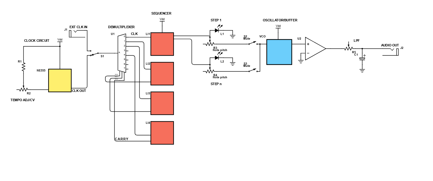
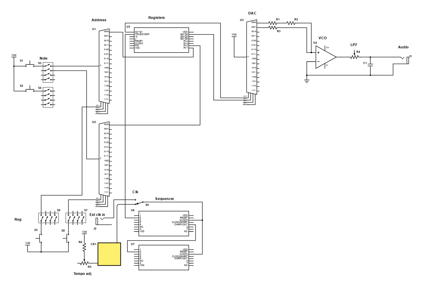
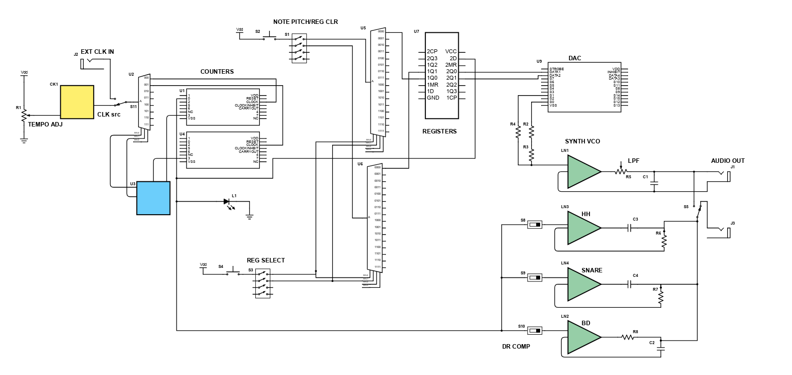
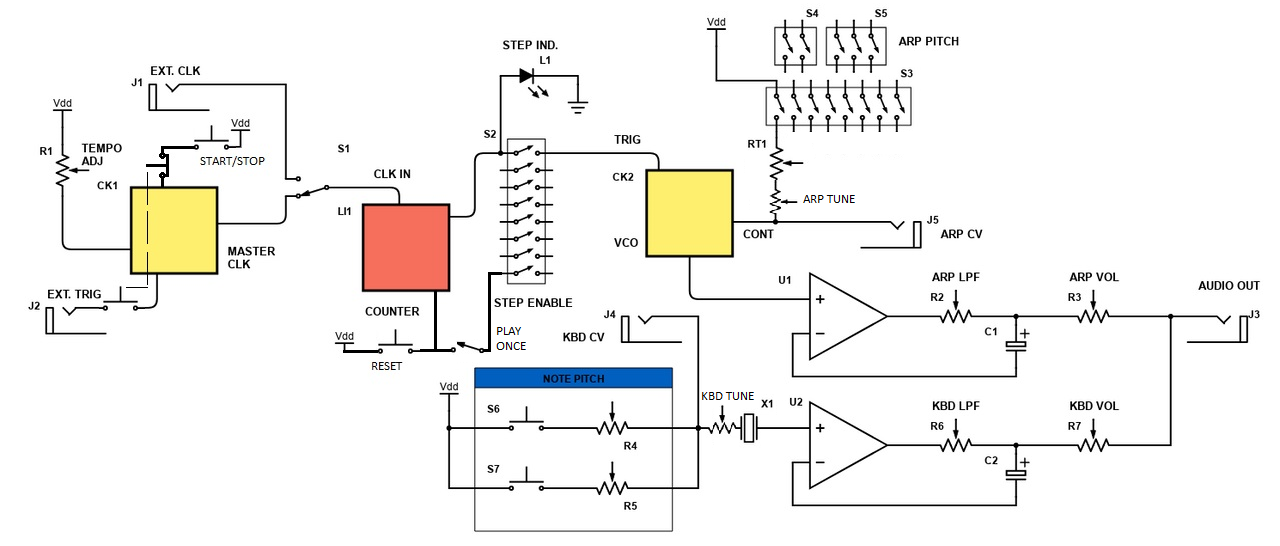
Basically, the device would use a NE555 timer which feeds the clock inputs of cascaded decade/octal counters (CD4017BE or 4022 for example) at an adjustable tempo (I built a metronome back in school which I recall uses the 555) so that while one counts it disables the other(s) by pulling the enable pin(s) high.
Each of the outputs would have a fader for adjusting the control voltage (note pitch) to an oscillator (another NE555, CEM3340 etc) and a mute switch as well as a step indicator LED in parallel. I was thinking a capacitor in series with either the timer or the outputs for adjusting the note length.
Other stuff I was thinking was:
-external clock input (A/B switch between the timer and an input jack)
-CV output
-reset
-low-pass filter (and an opamp to buffer the output)
-selectable waveform
-a more sophisticated system would use a counter per 4 steps instead of 8 as they perform a high/low cycle in the Carry out pin during the count (this removes the need to connect each individual step to the Enable pin)
Stuff I'd imagine that can go wrong:
-it only "ticks", ie. the control signals are too short; the capacitors could save this but the discharge characteristics can make it wildly unstable (or funky, who knows..) I have no prior experience working with counters to be honest.
-too low/high voltage PSU; I've read some theory behind analog 1V/octave synthesizers and while the IC's typically function in the 5-18V range the oscillator circuits require much less, ie. it may lack resolution to produce musically accurate results. To control one or two octaves with a 40..80mm fader isn't quite accurate but stuffing a huge step switch and a bank of 12-24 trimmers per 16 steps in a case is a soldering nightmare.
I hope someone gets my point here.. I can scan a drawn schematic for clarification (I have no access to a CAD for the time being)
Any thoughts?
-ef
PS. Here's a link to the original Arduino forum dev thread. I also came across a very similar DIY kit in Sparkfun (the SparkPunk Sound kit and the SparkPunk Sequencer kit, there's also a seemingly popular Atari Punk Console project hovering around the internet)
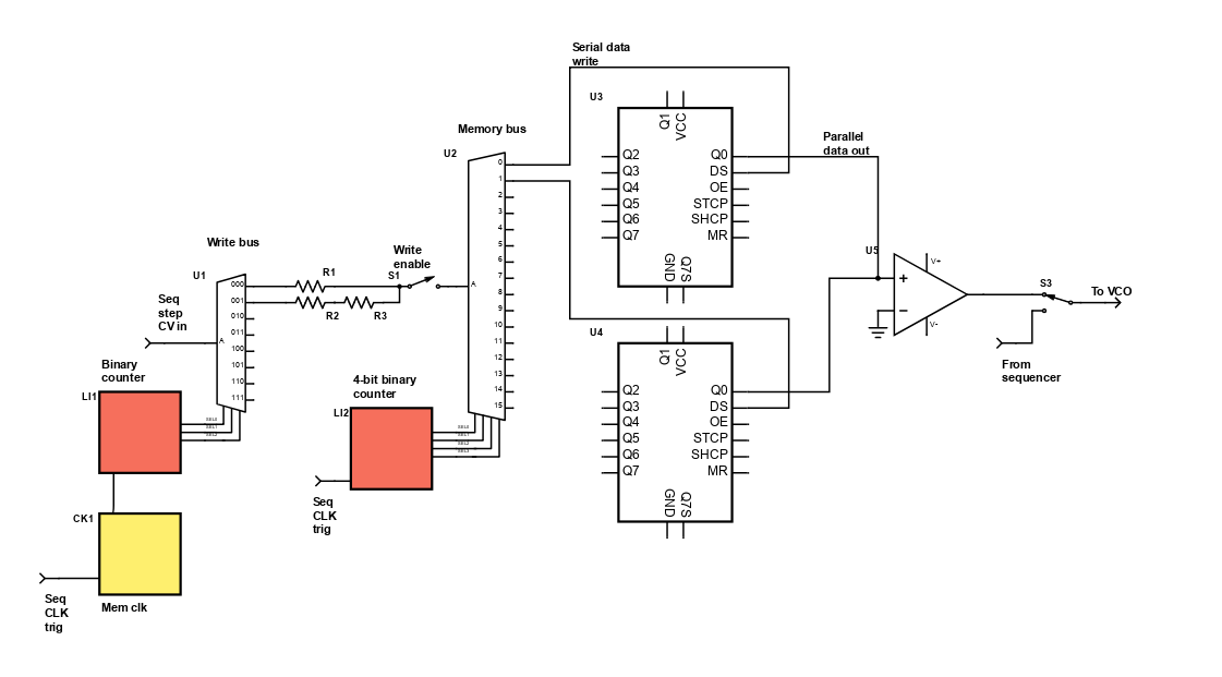
PPS. Regarding the initial design it's very simple, kind of like two bums fighting to a classic timer IC. The clock running into a 1-to-4 demultiplexer (74HC139 or 4052B for example) triggered by the 4th step of a counter and held high by the Carry out would be more sound because connecting the steps to the Enable pins sums them which may introduce crosstalk, this could be however fixed with diodes or summing resistors.


