Studer 1.022.363.00 transformer

GroupDIY Audio Forum

Help Support GroupDIY Audio Forum:

This site may earn a commission from merchant affiliate links, including eBay, Amazon, and others.

tata

Well-known member
Joined
Sep 1, 2013
Messages
171
Location
Hungary
can you please link me some information about this Studer 1.022.363.00 transformer?
i would like to use it as a 1:1 output transformer for a mic preamp.

these came from the 1.915.308 distribution amp, but schemo shows a different trafo there (1.022.363.81).

thank you

 
Hello
For what I understand, the last number in studer reference is some kind of revision, so the .81 don't change the characteristic of your trafo, like ration and impedance.
But I doubt this line out trafo have 1:1 ratio ?
Zam
 
If I remember correctly, Neutrik NTL1 was mentioned here in some threads as a direct descendant of Studer line transformer.
I know Neutrik NTM4 is used in clones of Studer 169 preamp, reportedly being the same as original.
Follow that information to find out if it's true.
Neutrik transformers are easily obtained through Thomann in Europe...

hope it helps...

:)

Luka
 
Luka,
You are right, the neutrik trafo NTL and NTM are used in some Studer pre (with specific Studer ref).
BUT as line or mic input NOT output. Tata is looking for line out trafo  :)
Zam
 
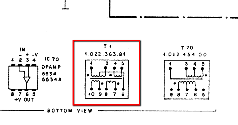
Studer_1-022-363-81_pinout.png

this is what the schemo shows, and found this info in another thread :

"I have measured the DCRs and they are 66R + 61R : 25R + 12R. The difference is obviously due to the length of the winding but I would imagine the number of turns/ratio will be the same."

is it ok to use pin 1-3 for input, and 7-8 and 9-10 as paralell outputs?
or for eg. 7-10 with 8-9 shorted for a boosted output?
 
Tata
I can't help you on this, I just have a quick look at the full schemo, and there is also something like a feedback in this trafo.
Zam
 
I know this is an old thread! But she lives again!

I think you are right on track, but you might want to parallel your inputs (tie 1+4 and 3+5) to get the gain boost along with wiring the outputs in serial (tie 8+9 and use 7 and 10 as your output.) That should give you a 1:2 ratio (150 ohm primary, 600 ohm secondary.)
 
I have four of these on a Dyaxis 2 pcb.
I’ve not touched them because I assume there’s a perfectly good circuit utilising the feedback there already, if I can get my head past all the extraneous a to d and cut some traces. PSU on The Dyaxis is two 24 v rails.
I have these photos that may be useful to someone.
 

Attachments

  • 1F05C987-FBD5-4AF4-989E-6E71B179E9CF.jpeg
    1F05C987-FBD5-4AF4-989E-6E71B179E9CF.jpeg
    713.4 KB
  • 8AFC9275-EEF4-4C35-9473-D612A0E6CEB4.jpeg
    8AFC9275-EEF4-4C35-9473-D612A0E6CEB4.jpeg
    371.2 KB
  • 6216B352-ADAE-468D-9856-9E3F5DA0F3FC.jpeg
    6216B352-ADAE-468D-9856-9E3F5DA0F3FC.jpeg
    395.3 KB

Latest posts

Back
Top