


nevercroak
Member
- Joined
- Jul 29, 2016
- Messages
- 11
To begin, many thanks to audiox for his work on the subject, EQ frequencies, gain steps and their documentation and bringing up the idea of building these in general! Not to forget the Studer engineers who developed this originally. audiox's version can be found here: http://groupdiy.com/index.php?topic=33996.0
What's in here (at the bottom):
- schematic
- components overlay
- BOM
- gerbers
(- text, images)
So, nothing of this is new - I'm just sharing a board layout I did (and tested a few hours ago).
Why this EQ? It's simple, works and work has been done on the subject, and I don't really know myself why else...
Design goals:
- Stepped Gain + Frequency selection
- only PCB mount components, nothing to "wire" (except PSU and audio connectors)
- Lorlin CK rotary switches to keep cost down
- small size to fit four in a 1RU modushop.biz enclosure
- no interference between high and low band corner frequency selection (in use)
- 169/961 topology per choice
- two parallel mounting positions for frequency selection capacitors
- frequency selection capacitors solder joints accessible when fully assembled
- option to insert additional circuitry after input stage and before output stage (M/S-Matrix for example)
- all through hole components (I don't really care but if somebody else wants to build, they may care)
Goals have been met, except the "option to insert additional circuitry" does not accept standard pin headers and plugs (was at least not specified...) but can be used with wires soldered to the boards, and accessability of the caps solder joints is limited.
General:
The layout is no work of art and does not even follow some basic layout rules, but it works and is quiet. This is not home etchable as it includes vias as space was at a premium when using THT components.
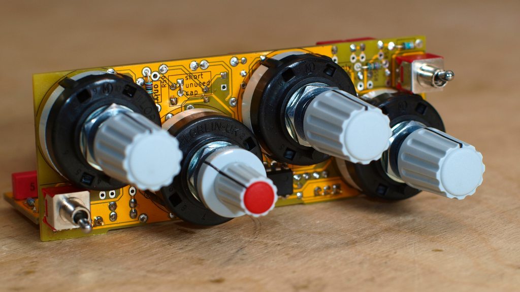
High and low frequency selection has been reduced to three frequencys to save space with as small toggle switch, it is an On-On-On switch wired as 1P3T, not simple On-Off-On. Mid frequency has six steps. Gain pots are 11 steps.
Topology 169/961 is selecteable by placing the right components in the right places. Dimensions are ~100x38mm. Can be used unbalanced when the input/output board is not used - preferably have some electrolytic cap somewhere not to remote from the board in this case.
The gerbers are an updated version of the board layout, the prototyped boards had one connection missing as one wire was not connected in the schematic. Gerbers are made to manufacture one board that has to be cut in two.
The .pdf includes a schematic, a print of the board with components value overlay (old pcb revision but only one trace has been added, so no issue for assembly) and a BOM. Components overlay and BOM show part values for gain steps: +/- 1,2,3,6,15 dB taken from audiox's mastering version of this EQ, and capacitor values correspond to (roundabout); Low: 25Hz, 50Hz, 120Hz - Mid: 145Hz, 250Hz, 550Hz, 1,5kHz, 3kHz, 6,2kHz - Hi: 12kHz, 16kHz, 20kHz
Capacitors for high and low band have been selected per audiox's selection charts; keep in mind here, that half the high frequency selection capacitors values summed are in parallel to the low band selection capacitors and their size influences your low band frequency choices. The mid band frequencys have been determined by simulation - accuracy has still to be proven.
Assembly:
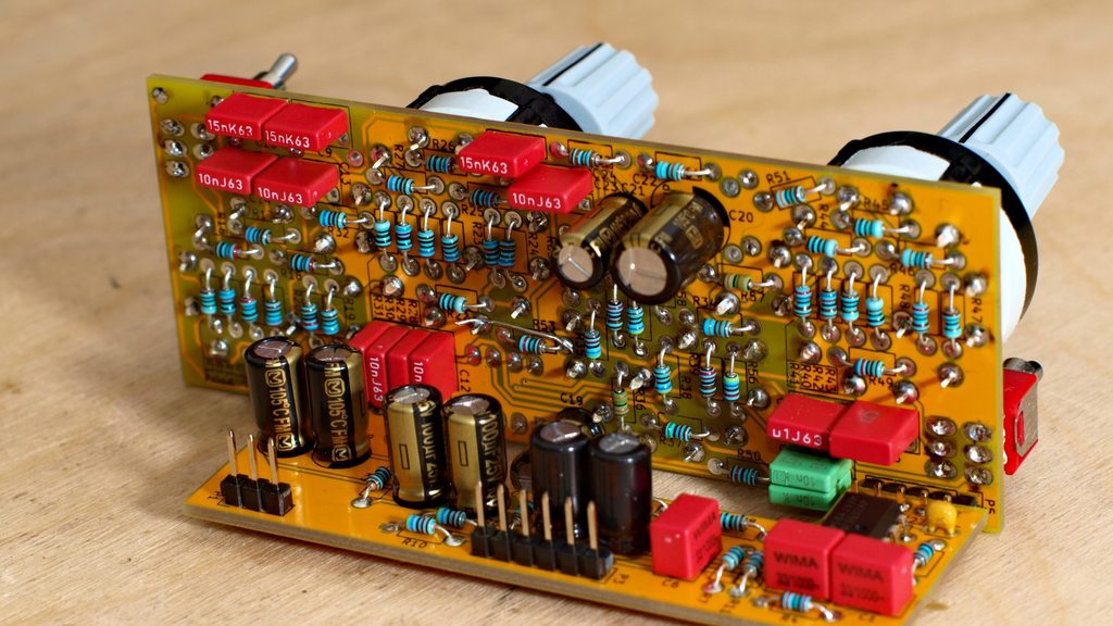
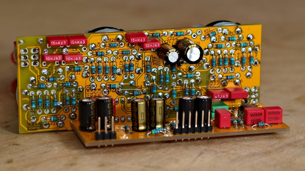
169/961 topology: there are two sets of resistors and two sets of capacitors where you have to populate only one in each, refferr to the schematic for this, the pairs of components in question are indicated on the boards silkscreen print as well. In case of the electrolytics capacitor pair, the unused/-populated cap has to be shorted/bridged!
Hole spacing for resistors is 7mm, ~3,5mm resistors (mostly 250mW) fit without problems, even ~6mm resistors (mostly 400-600mW) should fit - not guaranteed!
Assembly of the input/output board is traight forward.
The "main"-board is a bit tricky, this should bring you all the way easily:
1. resistors first
2. everything except switches and electrolytics
3. switches, rotary and toggle
4. electrolytics
5. connect boards
You may want to cut just a bit of plastic from the clips on the bottom of the Lorlin switches to get them about 0.5mm closer to the board, and solder the toggle switches so they are sitting above the PCB. Why: The toggle switches are a bit low profile and have a quite short lever (Multicomp 2MD6T2B2M2RE - I could not find any better ones, suggestions are welcome) and you want them to stick out a bit to be usable. In this case the front plate drilling should be tight to ensure structural support.
Another note: I would not advise to use knobs bigger than 15mm in diameter.
PCBs:
For now I have no plans on getting more PCBs manufactured, but if there is request I may do - preferably for people in Europe, I don't know if shipping to somewhere else is worth the cost.
Right now I have 8 PCBs left, the design flaw is a quick fix with one of your cut resistor legs, if somebody is interested tell me.
Final words:
Have fun with this, hopefully someone will find this useful.
Please no commercial use of the design! If you want to, contact me.
I may not be held liable for you burning down your house or wasting your money (or any other injury and damages caused) by building these.
-Arne
Gerbers: https://drive.google.com/open?id=0B04-cBBR4vMWaV84VVVMUERqYXc
Schem, overlay, BOM: https://drive.google.com/open?id=0B04-cBBR4vMWX0JUcWhNTVItd3c
Spot the fix:


") , but in the end I got them from Gustav.
, but in the end I got them from Gustav.