The problems are not removed till now :-[ Need help.
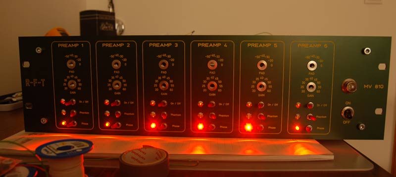
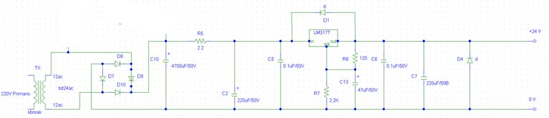
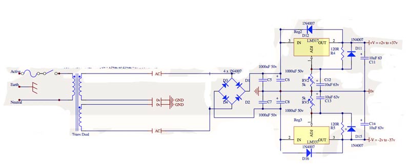
Like I wrote, the LED's getting darker and darker, if I switch on more and more. The problem isn't there, when I put on a ready built (bought) PSU on the circuit! So it must be a problem with my self-built PSU. For my self-built PSU I used LM317 to get +12V. Since my first postings I tried out two different circuit-designs. First the shown design from JLM, second a one rail design without the -V rail and other input capacitors. Both don't work. I changed the transformer too. First I used 25V / 1A second a 24V / 1,25A. With the bought PSU the LED's need not more then 130 mA if all are switched on. That should not be a problem for the transformer (1 A is more then enough). I wonder too that the voltage looks fine without load. It seems that LM317 (1- adjust; 2-out; 3-in) don't regulate with load? I don't know what should be wrong. Any ideas?


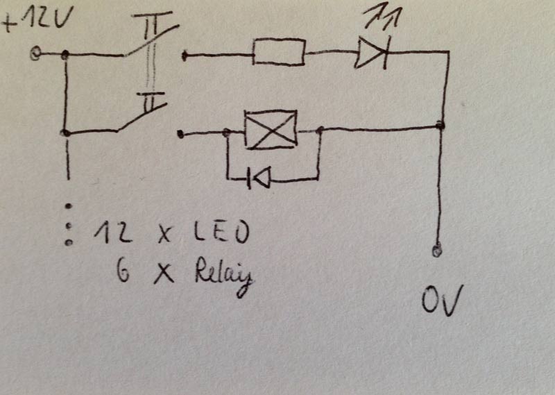
 This should not be in a parallel circuit so I think it must be a problem with the PSU.