


I have been working on the design of a signal amp for the EF85 compressor from scratch project.
I can have one tube/side in push-pull or say four/side and adjust the plate resistor to suit. The configuration not only alters the overall tube parameters (mu stays the same, gm x 4, rp/4) but it alters the output impedance from the tubes that the output transformer sees. This is especially relevent under gain reduction as the rp rises. see table.
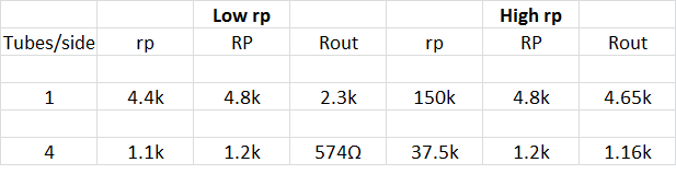
I know that the primary inductance affects the low frequency response, but I'm not totally sure what causes the high frequency roll off, I'm guessing its the primary leakage inductance/capacitance but I would like some expert input here.
Edcor Data table below with my figures.
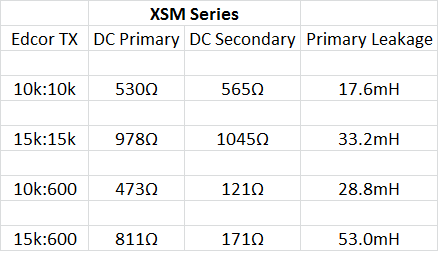
I have found that the lower the output Z, the better the frequency response range. I have been following PRR's logic from here,
http://groupdiy.com/index.php?topic=30349.msg368001#msg368001. but a 10kTX as he suggests has too poor a response with one tube/side (triode wired), 4 tubes is ok.
Expert input please
Best
DaveP


")