Transformer testing question

GroupDIY Audio Forum

Help Support GroupDIY Audio Forum:

This site may earn a commission from merchant affiliate links, including eBay, Amazon, and others.

jrmintz

Well-known member
Joined
Jun 4, 2004
Messages
998
Location
NY
I have a couple of these transformers:
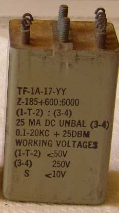
2B2.jpg


I hooked a signal generator up to the primary and my audio tester to the secondary and expected to see a voltage difference the same as the turns ratio. Instead I got what seemed very close to 1:1. Am I doing something wrong here?

Thanks
 
Well, 600:6000 is impedance ratio, so voltage ratio is sq root of that, or sq root of 1:10 = about 1:3.16.

Are you using the same meter to measure both sides?

A scope will read peak to peak and a DMM will read RMS.

You can drive it backwards, hook yhe gen to the 6000 ohm winding.

1 khz.
 
Thanks guys,

You can drive it backwards, hook yhe gen to the 6000 ohm winding.

That's what is really strange - it seems to read the same either way. That's why I think my methodology might be flaky (I've suspected that for years, but that's another story)

Can your signal generator properly "drive" the winding you are testing at the frequency in question?

I think so. It's an Amber analyzer. I'm putting in -26dbm at 1K. I tried some 1:1 output transformers I have lying around and they behaved as expected. BTW, the 185 ohm winding meaures about 14 ohms resistance, the 600 ohm winding 47 ohms, and the secondary about 450 ohms.
 
:green: :green:

I'm trying to figure out what they're good for, besides dissecting.

:thumb:
 

Latest posts

Back
Top