


earthsled
Well-known member
Greetings!
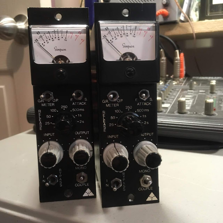
I have a pair of Trident limiter/compressor modules in for racking. I'm searching for more information about them – possibly schematics or a calibration procedure.
Some threads about this model:
https://groupdiy.com/index.php?topic=40973.0
https://groupdiy.com/index.php?topic=25611.0
https://groupdiy.com/index.php?topic=57897.0
http://repforums.prosoundweb.com/index.php?topic=22707.0
Similar model:
https://groupdiy.com/index.php?topic=42579.0
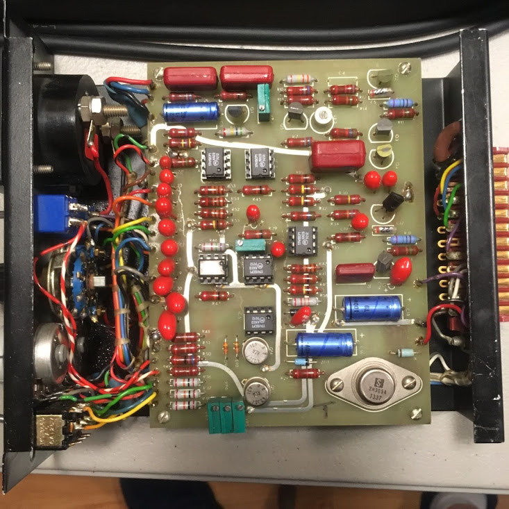
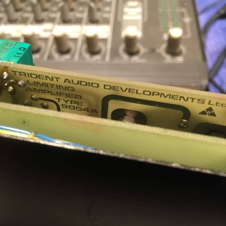
From what I understand, these modules are fairly rare and possibly made by Audio & Design Recording. The PCBs are labeled 9054A (upper) and 9054B (lower). The power supply is +48 volts. Q1 is a 2N5458 (jfet) and the small-signal BJTs are BC413 / BC415 complimentary types. The six opamps are 741 types.
The modules seem to be working okay, but the calibration seems off – especially when linked. The GR meters respond differently when the same test signal is applied to one side or the other.
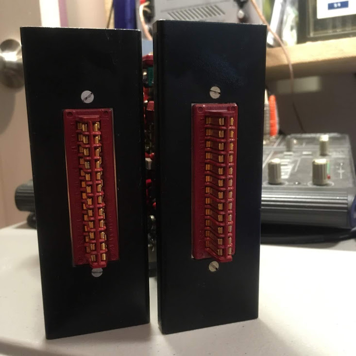
These units came with an external linking switch that connects pin 20 on both units. The internal "mono/couple" switch is inoperative, but I can see this switch directly connects to pins 16, 17, and 18 (making continuity with the upper PCB when in "couple" mode). There are three 5k trimpots on the PCB for these corresponding signals as well.
From what I can tell, the "in/bypass" switch works, but only audibly. The meters still show GR when in bypass mode. Maybe this is normal? I'd love to re-wire these switches so that the bypass would disable GR. This would be especially helpful for calibration.
If anyone has info on these modules, please share! Thanks in advance!
I have a pair of Trident limiter/compressor modules in for racking. I'm searching for more information about them – possibly schematics or a calibration procedure.
Some threads about this model:
https://groupdiy.com/index.php?topic=40973.0
https://groupdiy.com/index.php?topic=25611.0
https://groupdiy.com/index.php?topic=57897.0
http://repforums.prosoundweb.com/index.php?topic=22707.0
Similar model:
https://groupdiy.com/index.php?topic=42579.0
From what I understand, these modules are fairly rare and possibly made by Audio & Design Recording. The PCBs are labeled 9054A (upper) and 9054B (lower). The power supply is +48 volts. Q1 is a 2N5458 (jfet) and the small-signal BJTs are BC413 / BC415 complimentary types. The six opamps are 741 types.
The modules seem to be working okay, but the calibration seems off – especially when linked. The GR meters respond differently when the same test signal is applied to one side or the other.
These units came with an external linking switch that connects pin 20 on both units. The internal "mono/couple" switch is inoperative, but I can see this switch directly connects to pins 16, 17, and 18 (making continuity with the upper PCB when in "couple" mode). There are three 5k trimpots on the PCB for these corresponding signals as well.
From what I can tell, the "in/bypass" switch works, but only audibly. The meters still show GR when in bypass mode. Maybe this is normal? I'd love to re-wire these switches so that the bypass would disable GR. This would be especially helpful for calibration.
If anyone has info on these modules, please share! Thanks in advance!