


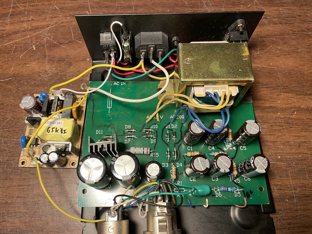
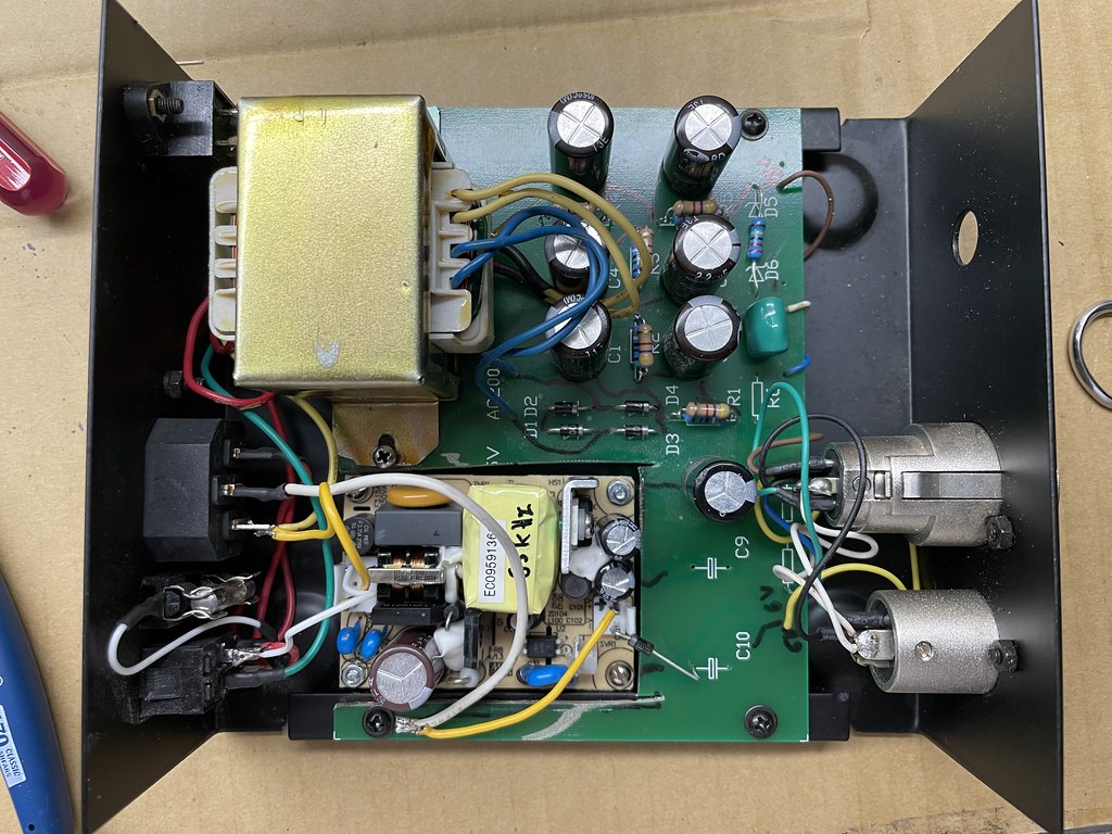
Standard Chinese tube mic power supply, with a 1A rated LM7806 that has a heatsink on the 6V filament supply. These seem to be used with 300mA filament tube mics.
I'm putting it in service with 600mA filaments, and am wondering if it's advisable upgrading to a 1.5A rated L7806. Is constant current at 60% rating going to cook this thing over time? I know, it's down to the heatsink, and no idea how I'd assess that outside of prolonged heat testing.
The existing regulator seems to do the job fine in medium duration testing, but I've not let it burn all day in a tracking session. The power transformer isn’t showing any decreased output from the load.
10 minutes in, I can't touch the heatsink. Probe I have is too big, it's leveling out at 120F, it's definitely hotter than that.

")
