Tube Preamp pedal + DI Output question

GroupDIY Audio Forum

Help Support GroupDIY Audio Forum:

This site may earn a commission from merchant affiliate links, including eBay, Amazon, and others.
- C12 is necessary because pin 2 of the opamp is set to  4,5V by R16. You don't want that voltage across the master and you don't want it at the other output.
- Leave out R20.
- And maybe add a 10k to ground on pin 2 and 3 of the XLR, particularly when you expect there could be phantom power switched on.
 
volker said:
- C12 is necessary because pin 2 of the opamp is set to  4,5V by R16. You don't want that voltage across the master and you don't want it at the other output.
- Leave out R20.
- And maybe add a 10k to ground on pin 2 and 3 of the XLR, particularly when you expect there could be phantom power switched on.
Thanks Volker; exactly what I would have said.

In answer to your other question, in my original circuit  R8 does indeed control the gain of the circuit. The values listed are designed so that the nominal gain make up required for each EQ type is obtained with the pot at approximately the half way position.

Cheers

Ian
 
ruffrecords said:
In answer to your other question, in my original circuit  R8 does indeed control the gain of the circuit.
Excellent. Probably a very simple thing but I'm so happy when sometimes I "see" through the circuits..... ;)

volker said:
- C12 is necessary because pin 2 of the opamp is set to  4,5V by R16. You don't want that voltage across the master and you don't want it at the other output.
Of course!! Thanks for the explanation. Hopefully I'll see that next time... ::)

volker said:
- And maybe add a 10k to ground on pin 2 and 3 of the XLR, particularly when you expect there could be phantom power switched on.
Those are bleeder resistors meant to discharge the caps, right?

Thanks a lot to both of you for your time and help :)
Cheers
Sono
 
Stepping in late, just my 2cents (looking at last version):

* Why R18 & C15?

* With now half a TL072 as output-opamp, possibly better to increase a few resistors in value:
  R17,19  (1k... 2k2 each)
  R11,12  (100k each)

* You could also spend the remaining TL072 half for an inverting stage (to drive XLR pin 3), or put both halves in parallel (with summing resistors), or use TL071, or just leave it as is ;-).

* Be sure C8 has the proper voltage rating

* Since your DiodeClip switch also has an OFF-state: add a 10M-ish resistor from C8-pin2 to ground to lessen eventual clicks when switching to any of the ON-states

* Add a 10M-ish resistor from C2-pin2 to C3-pin2 (basically across the HighCut switch)

* Connect pin 3 to pin 2/wiper (for each of the MID & BASS pots) to maintain a DC-path when wiper dances around the track


Bye
 
clintrubber said:
Stepping in late, just my 2cents (looking at last version):

* Why R18 & C15?
Imprioves CMRR at high frequencies
* With now half a TL072 as output-opamp, possibly better to increase a few resistors in value:
  R17,19  (1k... 2k2 each)
Definitely not. These are there to protect op amp from capacitive loads. No need to be any bigger. Check out the original Rod Elliot article.
  R11,12  (100k each)
Possibly. They are only there to ensure a dc path for the caps.

Cheers

Ian
 
Hi ClintRubber,
Thanks for joining in :)
This is the original Elliott Sound article about impedance balanced circuits
https://sound-au.com/project87.htm#cheat

clintrubber said:
* Be sure C8 has the proper voltage rating
Sure. It's a film cap, 250v ;)

clintrubber said:
* Since your DiodeClip switch also has an OFF-state: add a 10M-ish resistor from C8-pin2 to ground to lessen eventual clicks when switching to any of the ON-states
On my vero board prototype I didn't have any clicks at all, but I'll keep an eye on it

clintrubber said:
* Add a 10M-ish resistor from C2-pin2 to C3-pin2 (basically across the HighCut switch)
Please could you explain what for?


clintrubber said:
* Connect pin 3 to pin 2/wiper (for each of the MID & BASS pots) to maintain a DC-path when wiper dances around the track
maintain a DC-path? Excuse my ignorance but I don't understand. Could you please explain? :)

Thanks :)
Cheers
Sono
 
Another simple question please:

I'd like to create separate PCBs or modules for each section of this project (preamp, cabsim and balanced Output) and be able to combine them at will.
I already know how to combine preamp + DI Out.

My question is:
If I want to add the cabsim between the preamp and the DI Out can I just plug it in directly before the DI out?
This is the schem of the cabsim alone:


This would be the cabsim plugged in between the preamp and the DI Out:


Thanks a lot for your time and help :)
Cheers
Sono
 
Hi,

sonolink said:
Hi ClintRubber,
Thanks for joining in :)
This is the original Elliott Sound article about impedance balanced circuits
https://sound-au.com/project87.htm#cheat
I guess the optional Zobel indeed makes sense, although you rarely see them for opamp-circuits (if it does for a poweramp, then why not for an output driver).
Initially thought it was a leftover from an earlier drawn transformer.

On my vero board prototype I didn't have any clicks at all, but I'll keep an eye on it

In case of the middle position of the switch (OFF), the C8-pin2 and all what's connected to it is in essence floating, so not defined Voltage wise. Cap leakage and other eventual leakage paths will give that dangling part a certain Voltage, which most likely won't be zero. Once you switch to one of the ON positions, the previously dangling part will now become 0 V (DC-wise), so could result in a more or less audible noise/pop.

Please could you explain what for?
Also for pop-reduction, just in case.

maintain a DC-path? Excuse my ignorance but I don't understand. Could you please explain? :)
Usage of the term DC-path in a tonecontrol is actually not the best way to explain. Let's simply say you'd want to have at all times that the resulting pot-value is one of the possible positions of the pot. If the wiper is bouncing around (during rotation, or who knows, the wiper has lost its downward pressure on the track and the stage is wooden and the PA too loud and placed on that wooden stage...), the pot becomes (for short successive moments) in fact an open circuit, with consequences depending on the circuit.

Now connecting the open (dangling) terminal of the pot to its wiper does not change your intended circuit, but ensures there's always at least the full pot-value present. It's common practice to do so, and comes for free.

Bye
 
ruffrecords said:
Definitely not. These are there to protect op amp from capacitive loads. No need to be any bigger. Check out the original Rod Elliot article.Possibly. They are only there to ensure a dc path for the caps.
Suggested R-value increase because now TL072 iso 553x was used. Making R11,12 too small needlessly eats away drive capability of the TL072, or potentially affects performance. Shown 10k values not yet critical, but since you have to pick a value anyway, they still do their job well at a higher value.

Bye
 
clintrubber said:
Also for pop-reduction, just in case.
Ok. I didn't notice any pops when testing the vero proto but it probably won't do any harm to follow your advice and prevent any popping. :)

clintrubber said:
Now connecting the open (dangling) terminal of the pot to its wiper does not change your intended circuit, but ensures there's always at least the full pot-value present. It's common practice to do so, and comes for free.

Thanks for pointing that out. I had no idea it was common practice but your explanation makes sense to me :)

Cheers
Sono

 
I'm updating the schem, trying to understand and learn here. Just a couple of question about ClintRubber corrections please:
clintrubber said:
* Since your DiodeClip switch also has an OFF-state: add a 10M-ish resistor from C8-pin2 to ground to lessen eventual clicks when switching to any of the ON-states
Is this to "drain" to GND the part of the circuit between C8 pin2 and the Switch when the switch is in the Off position?

clintrubber said:
* Add a 10M-ish resistor from C2-pin2 to C3-pin2 (basically across the HighCut switch)
I understand the purpose but not the way it works. Could someone explain please?

Thanks a lot for your time and help
Cheers
Sono
 
pretty please bump....

Can someone please answer my previous question on post #29 about building separate PCBs?
(https://groupdiy.com/index.php?topic=75656.msg961253#msg961253)

Thanks a lot for your help
Cheers
Sono
 
sonolink said:
I'm updating the schem, trying to understand and learn here.

Great, nice that you not just want to add this and correct that, but also want to know why.

Note that the things I brought up were not in the 'absolutely necessary' category, and as you've seen could also be debatable,
but while at it, before building it, why not add them to prevent those 'eventual things', especially since they're no/low-cost additions.
The notion of 'towards blameless' comes to mind, as I've seen it used by Douglas Self in the context of circuit design.

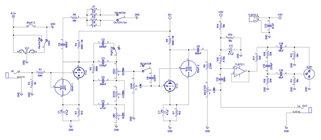
Just a couple of question about ClintRubber corrections please:Is this to "drain" to GND the part of the circuit between C8 pin2 and the Switch when the switch is in the Off position?

Yes.
Without further measures you won't have control over the signal-value at the time of switching, but the least one could do is to arrange that both nodes that will soon be meeting by the switch-closure (& bounce...) are at the same DC-value. (Note that 'same' is enough, it's not necessarily 0V)


I understand the purpose but not the way it works. Could someone explain please?
Same idea here.

Have a look at this schematic (of the link below) for instance, the 2M2 resistor across the BRIGHT switch.
(Likewise the 100k resistor near the THICK switch, same purpose)

https://www.audioservicemanuals.com/p/peavey/peavey-tg/1335415-peavey-tg-raxx-schematic


Bye
 
clintrubber said:
Great, nice that you not just want to add this and correct that, but also want to know why.

I always try to learn but at my age one does not have enough time to get an EE degree. So this place, reading and tinkering around is what I have left :)


Can PLEASE someone answer my other question on post #29?  :)
https://groupdiy.com/index.php?topic=75656.msg961253#msg961253

Cheers
Sono
 
sonolink said:
Can PLEASE someone answer my other question on post #29?  :)
https://groupdiy.com/index.php?topic=75656.msg961253#msg961253
Yes you can plug the cabsim between the two.
 

Latest posts

Back
Top