


Hi all,
I want to rack my V72 preamp and I want to add a PAD on the input. Source-impedance should be 150 Ohm and input impedance 2000 Ohm. I know that I could have someone calculate or build them for me, but I would really like to learn some more and DIY is much more interesting.
I read a lot through different forums but I'm still not sure, that I found the right way to do it. Maybe someone could share some details?
A) Output Impedance is more important.
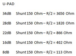
U-PAD with constant shunt resistor - That's what can be found in the V76 circuit diagram and the values of the resistors conform to the calculations / explanations from the Uneeda-Audio-Page http://www.uneeda-audio.com/pads/. My calculation:
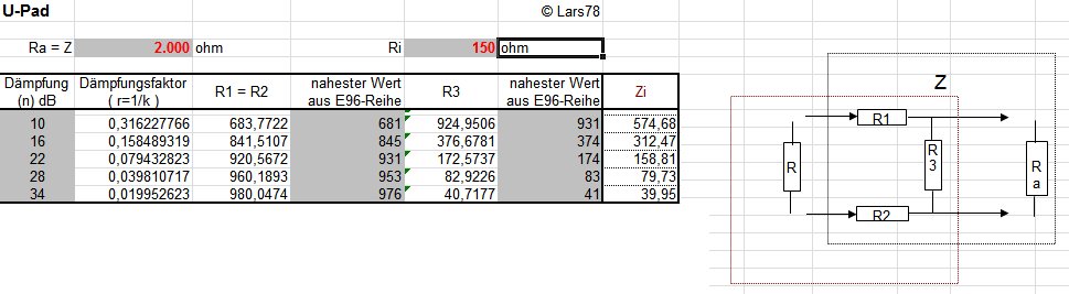
B) Input Impedance is more important.
U-PAD again. A calculator for this can be found here: http://starfishcoffee.de/u-PAD_calc_edit2.xls
My calculation:
C) Input and Output impedance are important
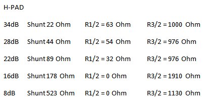
H-PAD - low attenuation seems to get difficult with this one as calculated values for the input-series resistor become negative (I did note 0 Ohm in my calculation below).
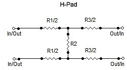
(using this calculator: http://www.nu9n.com/tpad-calculator.html)
My calculation:
Someone also mentioned a balanced bridged-T-attenuator, but my understanding is, that this is only designed to work between impedances of the same value.
I would really like to learn some more, so If anyone could share some insight on thisissue that would be great!
I want to rack my V72 preamp and I want to add a PAD on the input. Source-impedance should be 150 Ohm and input impedance 2000 Ohm. I know that I could have someone calculate or build them for me, but I would really like to learn some more and DIY is much more interesting.
I read a lot through different forums but I'm still not sure, that I found the right way to do it. Maybe someone could share some details?
A) Output Impedance is more important.
U-PAD with constant shunt resistor - That's what can be found in the V76 circuit diagram and the values of the resistors conform to the calculations / explanations from the Uneeda-Audio-Page http://www.uneeda-audio.com/pads/. My calculation:
B) Input Impedance is more important.
U-PAD again. A calculator for this can be found here: http://starfishcoffee.de/u-PAD_calc_edit2.xls
My calculation:
C) Input and Output impedance are important
H-PAD - low attenuation seems to get difficult with this one as calculated values for the input-series resistor become negative (I did note 0 Ohm in my calculation below).
(using this calculator: http://www.nu9n.com/tpad-calculator.html)
My calculation:
Someone also mentioned a balanced bridged-T-attenuator, but my understanding is, that this is only designed to work between impedances of the same value.
I would really like to learn some more, so If anyone could share some insight on thisissue that would be great!