


I've an old V72 wich sound thine with few bass,
so i'm going to recap it to give him a second life!
i found some schematics on google but with a bad definition and i don't have the partlist,
i will replace the 5 8uF 450v caps on the power supply board by 10uF (as other members here done before me),
but as i'm a newbie i wonder what else need to be replaced?
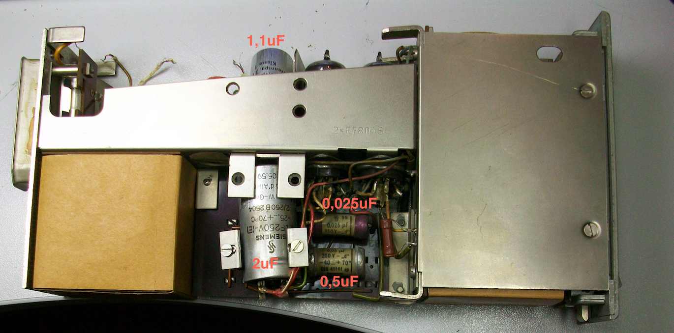
there are 1,1uF 3v ; 2uF 250V ; 0,025uF 250v ; 0,05uF 250v what do you think about them?
i also found a post where "Jean Clochet" explained :
"Many years ago I owned a REDD17 desk for a while.
The 1uF cap you're referring to is inbetween the windings and isn't really for blocking DC but is there to act as a rumble filter/low cut.
The cap is brought out to pins 2a & 2b on the rear tuchel connector so you can short it out if you want/need. In the REDD17 desk, the V72's used as mic amps had an additional cap strapped across pins 2a & b (it was a .25uF for 1.25uF total value) to lower the frequency of cut. But on the amps used as the mix and output amps, the cap was shorted out."
so maybe i could replace the 1,1uF by a 0,25uF to lower the frequency of cut?
and i found a schematic where it seemed to be a reaction loop or something like that (see in red), is that a variable gain mod?
here is the original schematic (i guess):
here is the other :
so i'm going to recap it to give him a second life!
i found some schematics on google but with a bad definition and i don't have the partlist,
i will replace the 5 8uF 450v caps on the power supply board by 10uF (as other members here done before me),
but as i'm a newbie i wonder what else need to be replaced?
there are 1,1uF 3v ; 2uF 250V ; 0,025uF 250v ; 0,05uF 250v what do you think about them?
i also found a post where "Jean Clochet" explained :
"Many years ago I owned a REDD17 desk for a while.
The 1uF cap you're referring to is inbetween the windings and isn't really for blocking DC but is there to act as a rumble filter/low cut.
The cap is brought out to pins 2a & 2b on the rear tuchel connector so you can short it out if you want/need. In the REDD17 desk, the V72's used as mic amps had an additional cap strapped across pins 2a & b (it was a .25uF for 1.25uF total value) to lower the frequency of cut. But on the amps used as the mix and output amps, the cap was shorted out."
so maybe i could replace the 1,1uF by a 0,25uF to lower the frequency of cut?
and i found a schematic where it seemed to be a reaction loop or something like that (see in red), is that a variable gain mod?
here is the original schematic (i guess):
here is the other :
")

![Soldering Iron Kit, 120W LED Digital Advanced Solder Iron Soldering Gun kit, 110V Welding Tools, Smart Temperature Control [356℉-932℉], Extra 5pcs Tips, Auto Sleep, Temp Calibration, Orange](https://m.media-amazon.com/images/I/51sFKu9SdeL._SL500_.jpg)


