I do not know.
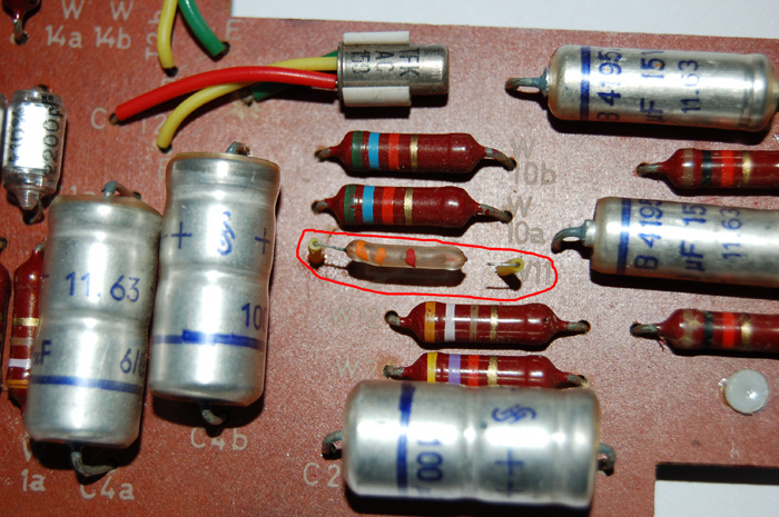
The part in your picture is very strange.
I found a
schematic but without voltage values. So this is guesswork.
The arrow implies a variable resistor. Usually we use a 3-leg potentiometer; however it could instead be a "selected" part, factory tested to work with the transistors on the board (and perhaps re-selected if a transistor must be replaced).
W9, W11, W12 set the base bias on T2a T2b. Why?
The collectors of T2a T2b must swing very large voltage to drive emitter followers T3-4a-b. I think the supply for T2 is 30VDC and for T3-4 is 12V. T3-4 must be forced 10V up and 10V down, we lose some voltage swing in W13 and W14, therefore we need the 30V supply for T2, and we need to set the collectors of T2 to idle very nearly half of that 30V supply.
I do not see any reason it needs to be temperature compensated. -Maybe- it needs temp to pass a strict German broadcast spec in extreme temperature, but not for a flavor preamp in a recording studio.
Select a resistor to make voltage at point "F" and "F
'" about half of the voltage at point "N". You can simply read voltages at W14a-b. One end will be about 30V. The other end, with W11 broken, may be about 5V.
I calculate that the "right" value of W11 is 2,000 for high-gain transistor and 3300 for a very low-gain transistor. This suggests using a 3K3 variable resistor, as the schematic shows.
But variable resistors, like potentiometers, are unreliable. Since you will not be changing T2a-b (if you do, you can change W11 at the same time), I think you should temporarily put in a 2K2 resistor.
Measure points F and F', compare to point N. If points F are too high, increase W11 to 2K7. Go to 2K0 or 3K3 if that is what it wants.
Points F F' do not have to be accurate. If N is 30V, then points F may be 13V to 17V and it will work fine. They could be 10V or 20V and it would still "work fine" but might not meet the original Max Output specification. If 2K2 is too small and 2K7 is too high, then 2K5 is perfect, or close enough for all practical purpose.
When you find a happy resistor, solder it in to last another 40 years.
Point F and point F' do not have to be exactly the same, though the difference should be less than 2V. There is no way to trim this. If they are very different, then T2a T2b are poorly matched, though they would have to be at the extremes of the Hfe=40-200 range to give trouble.


