we don't need no stinkin schematics....

GroupDIY Audio Forum

Help Support GroupDIY Audio Forum:

This site may earn a commission from merchant affiliate links, including eBay, Amazon, and others.

JohnRoberts

Well-known member
Staff member
GDIY Supporter
Moderator
Joined
Nov 30, 2006
Messages
28,522
Location
Hickory, MS
My replacement sump pump controller just failed again. First time it failed was coincident with a lightning strike nearby. When I contacted the manufacturer to return for warranty repair, they just sent me a new unit. Being a chronic pack rat I just kept the broken unit for spare parts.

I decided to open up the old first failed controller to look for something obvious... Ding, ding, ding... an old school 2n4403 (GP PNP) was shorted collector to base. I figure this was driving the relay coil and being shorted is consistent with controller relay being stuck always on... Kind of like my recent failure.

I was a little surprised that I couldn't find a 2n4403 in my back lab, I used them back in the day. My lab is populated with parts from a few decades ago,,, but I did find my bag of MPSA56 a GP PNP bipolar I standardized on, like a 2N4403, or 2N3906 just with higher breakdown voltage and better specs than the 4403.

In no great surprise it is now fixed and appears to be working properly... I even hear the 10 sec delay for the relay to disengage. This design uses a 555 timer to generate the 10 second delayed off, so cutting edge design for 40-50 years ago. ;)

JR
 
good ol Mom put labels on everything before she went. very spooky. pictures in the scrap book, you turn them over and it says, "uncle margaret, your fathers one legged stepchild-1934"
 
I've been recently helping clear out the workshop of a broadcast engineer who started in the late 40s and worked mostly for Radio Australia but also had his personal side business. Every time a workshop was moved or closed down it seems he collected their parts stashes and brought them home. Amazing collection of NOS obscure connectors, about 10 different collections of resistors and caps apart from the bulk bags of components. Then there's the actual equipment, old tape machines, all sorts of widgets and gadgets. I now have a lifetime supply of fancy knobs from bakelite to 'modern' Sifam collet and a couple of big boxes of assorted audio transformers, mostly Australian made. Still loads more to sort through, including the boxes of just random stuff. It's simultaneously intriguing, exciting and a lesson in not collecting too much stuff I'll never use and just leave behind for others to deal with.
 
.. it says, "uncle margaret, your fathers one legged stepchild-1934"
Darn, inadvertently I read this in a monty-python'esque voicing - and had my first coffee-theough-the-nose-experience in months..

Thanks.. I think.. My keyboard at least seem to still work, now it's dry

/Jakob E.
 
I forgot to throw in my TMI about selecting transistors for discrete designs. New designers fret too much over device selection perhaps because they have so many choices to pick from... Back in the day designers would generally have a short list of favorite active devices to use. I can almost date my sump pump controller design by the devices and components used. The controller used 2n4401 (NPN) and 2n4403 (PNP) general purpose transistor switches. The NE555 timer was invented in 1971 (Hans Camenzind) and pretty popular back then for almost anything. I suspect the sump controller was probably designed back in the 1970s and has been made in China so long it is now cheaper than dirt. As I already shared when this one failed, they just sent me a new one rather than try to repair it despite only pennies in parts cost. Labor and shipping is the larger story.

Back on the subject of bipolar device selection for simple discrete designs, common practice was for designers to have favorite pairs of complementary devices. Back in the 60s when I was first exposed to discrete design as a junior technician, the engineer's work I was supporting favored 2n2222 (NPN) and 2n2907 (PNP) for almost everything. Back then they were supplied in metal cans and would burn a nice red circle into your finger tip if you pressed too firmly checking for overheat. The old technician trick was put some spittle on your finger before touching the metal can. If the spit boils away, you know the can is >100'C.

By the 70s they started putting transistors in plastic (?) packages to reduce cost. Besides the 2n4401/4403 NPN/PNP complementary pair I also used 2n3904 (NPN) and 2n3906 (PNP) for general purpose, low level designs. Later I upgraded to higher voltage MPSA06 (NPN) and MPS A56 (PNP). I still have bags of 3904/3906 and A06/A56 in my back lab.

If I had a 2n4403 I would have used that for the repair, the MPSA56 having higher breakdown voltage shouldn't hurt. While I didn't trace out the circuit it looks like the transistors were driving the relay coil. The controller uses a relay to switch mains power to the pump. The obvious speculation is that voltage spikes from switching a relay coil may have precipitated the transistor failure. Shorted collectors are often caused by high voltage spikes. I think I saw a clamp diode across the relay coil but perhaps not adequate protection. It seems to me that a design in production for this many decades would be refined by now, that said the original designer may be taking a dirt nap by now.

JR
 
Today I swapped out my failed sump pump controller with the old one I repaired. My sump is now back on automatic pilot. The symptoms for the failed controller look similar but I didn't take it apart yet. If it has another shorted 2n4403 I will definitely revisit the design. I recall seeing a clamp diode across relay coil but it may not be fast enough.

I replaced the shorted 40V 2n4403 with an MPSA56 that is an 80V part so this could help (I hope).

JR
 
The symptoms for the failed controller look similar but I didn't take it apart yet. If it has another shorted 2n4403 I will definitely revisit the design. I recall seeing a clamp diode across relay coil but it may not be fast enough.

I'm looking forward to follow your repair on that one and to know if the failure is the same as in the other one
 
I will probably wait until it breaks again. It is a pain in the butt to swap it out. I have the float level switch assembly mounted directly to the pump housing, so have to pull the whole thing out from under my crawl space.

Last two failures took about one year each. Using the PNP as a high side driver to power the relay coil would generate a voltage spike in the right direction to exceed the collector voltage (40V in a 4403). I think I saw a clamp diode across the relay coil. The 80V MPSA56 PNP replacement could deliver a little more reliability. Shorted collector is a definite symptom of over voltage punch through.

For now I have to wait for it to rain again, to confirm it cycles on and off again, but living in MS I probably won't have to wait long.

JR

PS: Home repairs suck, fixing the same thing twice, really sucks. If there is a third time, there definitely won't be a fourth. I'll redesign that sucker.
 
I should have another year or more (hopefully more) before my sump pump controller fails again but since it was already removed I decided to check for the obvious failure candidate. Ding, ding, ding... shorted 2n4403 again. We have identified the weakest link. I checked around a little more and the relay drive circuit is not as simple as I hoped. Functionally this has a dual threshold float switch (perhaps magnetic/hall effect switches or maybe even magnetic relays). The controller turn on when water rises above threshold, and then keeps running for 10 seconds after water drops below threshold. I suspect the 555 timer is providing the 10 second stay-on delay. How that exact logic is executed is unclear without tracing out more of the circuit.

The 4403 pnp is shorted collector-base. I also measure a short from those two to the 4401 npn emitter whose collector is connected to the relay coil. I still suspect a voltage spike that occurs when the relay releases is doing the damage but likely passing right through the 4401 to punch through the 4403 collector. I looked at the clamp protection diode across the relay coil and the only 2 digits I could read off it was "07". It looks like a typical 1A rectifier so perhaps a 1n4007. For this application the high voltage is not really useful and the switching speed of a rectifier diode may not be the best choice.

1n4148 has recovery times in the 5-20 nSec time. The 1n4007 is more like 2usec so 100x longer. This is still all speculation.

The obvious question is how can they afford to sell a flawed design? The PCB legend has a C date almost 20 years ago, and this may have been made in china even longer. They appear to be playing the odds of customers losing interest in warranty claims.

I suspect a few different component choices with pennies increased BOM cost could make this more reliable.

Time will tell.

JR
 
I am probably overthinking this as I sometimes do. For several days I have been doing web searches for typical or recommended circuits. I found at least one recommendation to use 1n4007 and a second link saying that 1n400x rectifiers are way too slow to use. :unsure:

I should probably stick a fork in this until the next time it fails (should be a while).

JR
 
Well not exactly perfectly, I am getting some short cycling and I can hear it pulling air during the 10 sec delayed turn off. I need to tweak the pump level threshold a little higher so it pulls water for the full 10 seconds. I also noticed a bunch of pin hole leaks in the 1 1/4" discharge hose, last winter some of those pin hole leaks turned into gushers.

I don't need the full flow of the larger 1 1/4" diameter discharge hose, a much cheaper garden hose will be adequate and cheaper to maintain. I still have the original adapter to 3/4" GHT. I have a 3/4" check valve (back flow preventer) on order and some new screw clamps for remounting the level sense float switch. The old stainless steel screw clamps I used last year are rusty (WTF).

JR
 
Over the weekend I pulled out my sump pump and tweaked the float switch a little higher up to prevent it pulling air at the end of cycles. The controller runs an extra 10 seconds after water falls below threshold.

I also removed the 1 1/4" discharge hose and converted back to Garden hose (3/4" fittings, maybe 5/8" diameter hose?). I installed the back flow preventer-check valve between two 50' garden hose lengths. I didn't mount it directly on the pump down in the crawl space in case it didn't work properly and required servicing. The check valve may reduce flow too.

Finally got enough rain to give this a proper test. It appears to be working properly. (y)

The water flow rate is obviously a lot lower, and I notice that the pump power draw is less with the smaller discharge hose (260W vs 300W with larger discharge hose).

All good for now, until the next failure...

JR
 
In case I haven't beat this to death with too much info...

I am reaching the conclusion that the apparent short cycling was because the larger discharge hose allowed the sump pump to move so much water so quickly that the modest sized depression (well) down in my crawl space would empty out quickly and cut off the pump, while ground water continued to flow into the depression. Now with the restricted garden hose discharge it pumps water out much more slowly eliminating the apparent short cycling. I have more than enough capacity to clear out my crawlspace even at the lower flow rate over several hours a day.

Last night because of freezing weather (including snow) I turned off the sump pump in case water in the hose froze solid. At noon when temperatures were above freezing, I turned it back on it ran for over an hour. It never ran that long with the higher flow rate.

Rather than turning it on and off manually which kind of defeats the purpose of a float level controller. I have incorporated a TOD timer switch. I don't turn it on until 11am and off at night time. I can manually override the TOD box with always on, and another switched outlet strip for always off.

I am looking forward to putting this into the cybernetic control, don't worry about it...

JR
 
Still trying to make my sump pump system fully automatic (right now I have it turned off because water froze in the discharge hose).

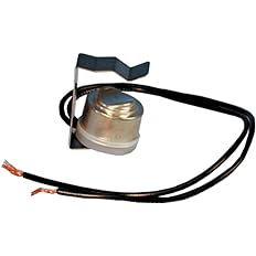
I found a "freeze protection controller 10A switch that opens at 35F and closes at 50F.... this is used in to protect airco evaporator coils in freezing weather.
61mWQWe10YL._AC_UL232_SR232,232_.jpg


I could take apart the float level controller and wire this in series, or just keep it separate.

Temp outside right now is 32F so I'm not doing anything outside for now.

JR

PS: Since it appears that the short cycling was not back flow from the discharge hose, I just removed the 3/4" check valve, to see if the flow rate improves without that inline. Later after things warm up.

Edit-update... with the check valve removed the water flow is much improved. It took 20 minutes to clear the overnight accumulation of water... It has stayed off since, so the discharge hose back flow was not a problem.
 
Last edited:

Latest posts

Back
Top