What's goin on with this Output?

GroupDIY Audio Forum

Help Support GroupDIY Audio Forum:

This site may earn a commission from merchant affiliate links, including eBay, Amazon, and others.

Philip_BlueFX

Active member
Joined
Feb 27, 2020
Messages
28
Location
Ελλάδα
Hello community. Name's Philip and as you can see I am brand new here.
I'm gonna start off with this little shout out for help from the experienced.

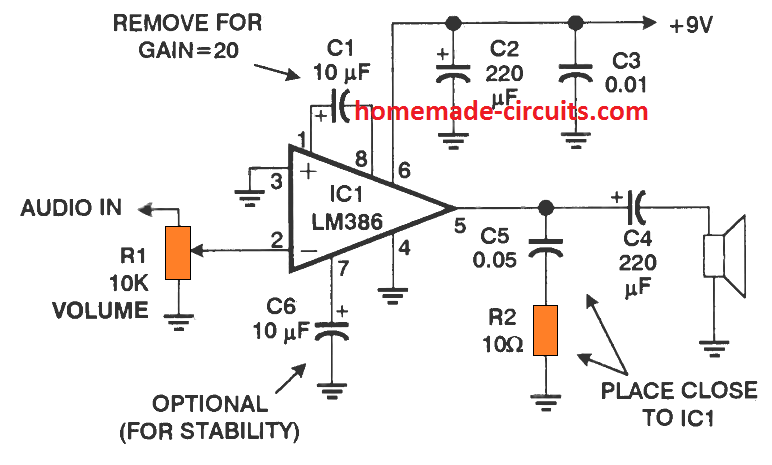
I have this little LM386 based amplifier on breadboard, just messing with my new oscilloscope.
LM386.png


So here's my question.

Input is 1Khz 10V Sine wave.
I plug a 6Ohm, w/e Watt speaker on the output (ohms is as I measure with my DMM. Got no clue on the actual data).
Attached is a picture of the input-output scope. On the left is without the speaker, on the right is with the speaker.
I can not understand how the output amplitude can be lower than the input while the sound volume is significantly louder.
Also, when I first power the amp (without a speaker), I get the left version of the graph, where it looks as if the wave rides on a DC offset. However, when I plug in the speaker, the (what I understand as a ) DC offset disappears and stays this way even if I unplug the speaker.

To clarify. Input is the yellow line and output is the blue line and my supply is 9V through a Twintex bench supply.


Attachments

  • both.PNG
    both.PNG
    1.9 MB · Views: 22
Ohm's law, basically. Or rather, power.

The input signal may be higher in amplitude, but the currents involved are tiny (likely microamp-range), while the impedances are relatively high (tens or hundreds of kiloohms), thus the powers are in the microwatts.

On the speaker output side, despite the lower voltage amplitude, the load impedance is in the single digits, so the power is significantly higher (by orders of magnitude).

That being said, without the amplifier and speaker, the loudness is actually zero, or inexistent, wouldn't you agree? ;)

Regarding the DC offset, with the speaker side of that DC-blocking capacitor floating, that will drift up to whatever the voltage is on the amplifier side.
 
Op amps have very low output impedance but in practice they have internal resistances that become a factor when you try to draw a lot of current from them. LM386 is a little unique in that it's more of a power amplifier than an op amp but it too has limitations. So there are at least 3 factors to consider in this case. One is drawing too much current will cause an output drop. Two is that internally the amp might have limitations as to how far the output can swing. There are fancy modern "rail-to-rail" op amps that can swing to within mV of the supply but not an old crappy device like an LM386. Third would be that even if the op amp were perfect, it cannot produce more current than the supply. So if your bench supply has some kind of current limiting, you're going to get a drop in the supply voltage which will be reflected in the output. Think about how much power you're trying to dissipate. I assume by 10V you mean 10V peak-to-peak so say 5V peak positive or negative into what is probably an 8 ohm speaker so that's 5V / 8R = 625mA * 5V = 3.125 W. An LM386 can't do that. Look at the plots in the datasheet. It's like you're driving an old car and it won't go any faster even though you have the gas pedal all the way down.
 
Wouldn't "overdriving" the LM386 (or hitting the power supply's current limit) show up as clipping, though? As opposed to "just" the attenuation seen here?
 
No output impedance specs anywhere (TI or NatSemi datasheet), nor any output resistors anywhere in the internal schematic, so......
 
Khron said:
No output impedance specs anywhere (TI or NatSemi datasheet), nor any output resistors anywhere in the internal schematic, so......
That's not how op amps work. Op amps are networks of current sources / sinks. If a current source load turns off enough that it doesn't draw enough current from the current source, strange things start to happen. On outputs, the current limiting causes a voltage drop for obvious reasons and internally it limits voltage swing. If the current sources are operated within their linear region, then the op amp behaves ideally.
 
Khron said:
No output impedance specs anywhere (TI or NatSemi datasheet), nor any output resistors anywhere in the internal schematic, so......
It's an old part and simplified design.

I am not trying to blind you with science but a little deeper inspections about how active amplifiers and NF work. First a quick (simplified) definition of open loop gain (Aol). For an active amplifier to change X volts at its output, it will require X/Aol differential input voltage. This differential voltage is between the + and - input pin. For a lightly loaded modern op amp this differential voltage between input pins could be microVolts.  For a power amp chip I expect requiring much more differential input voltage. Visualize what is going on inside the amplifier IC. With no load the output stage is idling along requiring minimal drive current. With a heavy speaker load, the output stage needs more drive current. For the input stage to send more drive current to the output stage it requires more differential voltage between input pins. This input voltage gets subtracted from the signal input and the result multiplied by NF factor. More load, subtracts more voltage from the input resulting in less output.

I looked through tens of pages of data sheet and not one proper Bode plot (Aol) let alone Aol vs output load. 

Sorry I don't mean to confuse you, but the chip is probably behaving as expected (the data sheet suggests a minimum load of 32 ohms). 

JR
 
JohnRoberts said:
For the input stage to send more drive current to the output stage it requires more differential voltage between input pins. This input voltage gets subtracted from the signal input and the result multiplied by NF factor. More load, subtracts more voltage from the input resulting in less output.
Noted and interesting but at the risk of being overly pedantic, that's not what's happening here. There's ~9Vpp on the input of a circuit with a gain of at least 20x and the output is only maybe 5Vpp. That's the output current limiting.
 
Hey guys, thank you for all the replies.

It's actually true that 10Vpp input IS a tad too much for the LM386.
The same experiment with ~120mVpp, reads about 400mVpp on the output.
Also, measuring the output current with my DMM, I found that @120mVpp-In, Iout=40mA (while  input current is some μΑ).
Raising the input voltage to 10Vpp, I found out that the output current tops up at about 200mA (where my DMM reaches it's limits actually), way before amplitude reaches 10V.
So there we go, I was operating way above my limits, hence the "strange" (for my baby eyes) behavour.

Now to reply on some comments.
Khron said:
Wouldn't "overdriving" the LM386 (or hitting the power supply's current limit) show up as clipping, though? As opposed to "just" the attenuation seen here?

It actually clips both ends if I raise the volume pot but it happens with a mV input as well. That's because I am not reaching the limits of headroom (meaning Voltage amplitude limit), but the limits of current the chip can provide.

JohnRoberts said:
Sorry I don't mean to confuse you, but the chip is probably behaving as expected (the data sheet suggests a minimum load of 32 ohms). 

JR
I am on about 6 Ohm Load here and I believe that most commonly a 4-8 Ohm Load is to be expected for a speaker output.
You speaking about 32 Ohms minimum load had me confused, really.


Now on 120mVpp Input, I started raising the pot volume and observed my output (voltage) clipping on the negative side WAY earlier than the positive side. It looks like hitting a brick wall limiter, on the negative side though only.
Any comments on this?
 

Attachments

  • 118610467_1850174705122942_8001519866658891564_n.jpg
    118610467_1850174705122942_8001519866658891564_n.jpg
    109 KB · Views: 6
Philip_BlueFX said:
Hey guys, thank you for all the replies.

It's actually true that 10Vpp input IS a tad too much for the LM386.
The same experiment with ~120mVpp, reads about 400mVpp on the output.
Also, measuring the output current with my DMM, I found that @120mVpp-In, Iout=40mA (while  input current is some μΑ).
Raising the input voltage to 10Vpp, I found out that the output current tops up at about 200mA (where my DMM reaches it's limits actually), way before amplitude reaches 10V.
So there we go, I was operating way above my limits, hence the "strange" (for my baby eyes) behavour.

Now to reply on some comments.
It actually clips both ends if I raise the volume pot but it happens with a mV input as well. That's because I am not reaching the limits of headroom (meaning Voltage amplitude limit), but the limits of current the chip can provide.
I am on about 6 Ohm Load here and I believe that most commonly a 4-8 Ohm Load is to be expected for a speaker output.
You speaking about 32 Ohms minimum load had me confused, really.
Just reading the data sheet... probably a stability concern.
Now on 120mVpp Input, I started raising the pot volume and observed my output (voltage) clipping on the negative side WAY earlier than the positive side. It looks like hitting a brick wall limiter, on the negative side though only.
Any comments on this?

Looking at the waveform today the asymmetry in one polarity of signal swing suggests perhaps (current?) limiting.

JR
 
Philip_BlueFX said:
Now on 120mVpp Input, I started raising the pot volume and observed my output (voltage) clipping on the negative side WAY earlier than the positive side. It looks like hitting a brick wall limiter, on the negative side though only.
Posted picture shows the relation between power supply voltage, output peak-peak voltage for different loads on LM386 amp. 
Also, IMO you should test it in noninverted configuration and with resistive load. And gain should be calculated as ratio of output vs. input  voltage on input pin, not on input of a potentiometer.
@JR
Minimum load for LM386 is 4 ohms.
 

Attachments

  • lm386_power.png
    lm386_power.png
    43.4 KB · Views: 9

Latest posts

Back
Top