zero Z transformer mic inputs????

GroupDIY Audio Forum

Help Support GroupDIY Audio Forum:

This site may earn a commission from merchant affiliate links, including eBay, Amazon, and others.

rafafredd

Well-known member
Joined
Jun 3, 2004
Messages
2,412
Location
Rio, Brazil
from our friend Ted:

http://www.tfpro.com/index.php/page/M16

The microphone amplifiers are transformer input coupled with the input stage operating in class A. The input amplifier operates in current mode so that the input transformer works with zero flux giving extended bandwidth of 8Hz to 100KHz, unmeasurable 3rd harmonic distortion within the audio band, and noise performance equivalent to best conventional circuits.

It has been said here that noise would be a big problem, so i´m just wondering, how did he do it?

It would be a good way of getting a very clean signal with lots of input headroom plus all the benefits of transformer isolation, like infinite (mostly) CMRR, ground isolation, and all, and not worring about electronically balanced front end.
 
[quote author="rafafredd"]from our friend Ted:

http://www.tfpro.com/index.php/page/M16

[quote author="M16"]
The input amplifier operates in current mode so that the input transformer works with zero flux[/quote][/quote]
I guess we should discern between

(1) 'current mode inputs' and

(2) input-TXs working with zero flux.

That's at least how I understand it; these two things are not necessarily the same. Various circuits I've seen using TXs with zero flux had input-resistors in series with the primary, so the resulting input was 'a normal one' again. PRR scanned & posted a few interesting pages on the subject years ago, I must have the file.

The M16-spec doesn't state an input impedance, but does it in terms of: suited FOR 200 Ohms.
Don't recall if more exact circuit-specifics have been around here, I thought they were, but I'm not sure we could simply call it a zero-input impedance input (it does feel like some virtual earth topology though).

Bye,

Peter
 
Well, i´m sure it uses resistors for building up impedance here...

Audiox, do you have a schem from studer? Or at least, do you know what models did they used it in?

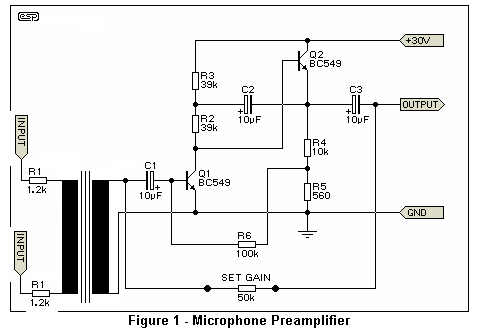
I´ve been thinking. There is this very easy one from Elliot:

http://sound.westhost.com/project13.htm

This mod should be simple enough to try out, just for the sake of it:

0Z_micpre.gif


I have VERY small, VERY high inductance yet low R mic trans I should trywith these. Good stuff, amorphous core, from modems... If it works good, oh, it´s an easy one for a transformer balanced live recording jig. An opamp at the output, for extra gain, and more current drive. Half a 5532.
 
[quote author="rafafredd"]

This mod should be simple enough to try out, just for the sake of it:

0Z_micpre.gif

[/quote]

Wow, I like it! :grin:
 
[quote author="Svart"]:shock:

It has Wavebourn's seal of approval... and it's simple...


The end is nigh!


:green:[/quote]

The end is a complex impedance device in feedback loop, so be careful! :grin:
 
Is there any danger of saturation or cutoff with Q1 at ground potential?

I'm wondering how to calculate the impedance of this thing, especially at Q1.
 
[quote author="Wavebourn"][quote author="rafafredd"]

This mod should be simple enough to try out, just for the sake of it:

0Z_micpre.gif

[/quote]

Wow, I like it! :grin:[/quote]

...I am just trying to understand...am I correct in assuming that the input resistors ( R1, 1,2k) are there to turn the transformer into a current sensing device instead of a voltage device. and that there are two of them( the resistors) only to not upset the common mode rejection?
johan
 
[quote author="Johan"][quote author="Wavebourn"][quote author="rafafredd"]

This mod should be simple enough to try out, just for the sake of it:

0Z_micpre.gif

[/quote]

Wow, I like it! :grin:[/quote]

...I am just trying to understand...am I correct in assuming that the input resistors ( R1, 1,2k) are there to turn the transformer into a current sensing device instead of a voltage device. and that there are two of them( the resistors) only to not upset the common mode rejection?
johan[/quote]

Yes. The higher is open loop gain, the lower is voltage on the transformer. The schemo in Samuel's link is different: there are combined feedback used there.

I'd use resistors before and after the transformer, to find a compromise for the particular transformer. I think the idea of modem transformers is brilliant, so I am going to try it later (too many things in my todo list, but big potential savings on transformers worth experimenting)
 
[quote author="Samuel Groner"]
There is this very easy one from Elliot:
I think the idea of modem transformers is brilliant.
You might consider calculating the resulting noise figure if you add two 1k2 resistors in series with the source impedance...

[/quote]

Yes, the same as in case of inverting opamp input.
 
We could go as lower as a pair of 500 ohms resistors for 1k total impedance seen by the mic, if it makes it any better noise wise.
 
With a 2k4 input impedance EIN is worse than -118.8 dBu; 1k get's us to -122.6 dBu at best. Good enough for condenser mics, but probably still a bit hissy for dynamics or ribbons.

Samuel
 

Latest posts

Back
Top