Not wanting to hijack this interesting thread, but what is the process for marking the front panel? I have a compressor that will need text and symbols.
[what is the process for marking the front panel?] -- Depends upon -- how/what -- it is that you want to have this done and/or you would like for it to look. Putting text and symbols onto a front-panel can be accomplish by:
1) Magic-Marker 2) Dymo-Label 3) Silkscreen 4) Engrave (mechanically or by laser) & White-Fill/Black-fill (my preference) 5) Crayon 6) Lipstick 7) Hammer and chisel & white-fill/black-fill
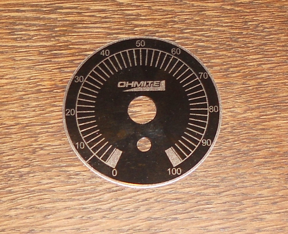
I had designed this rack-panel for its graphics and text to be "engraved & white-filled":
I worked out the angles for the switch positions and drew it on MS paint. I printed off copies and enlarged them until I got the size right.
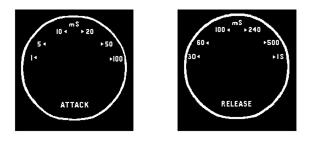
When it was finished, I drew a box around each one and coloured the text red. I was then able to paint the white parts black without losing the text.
Finally, I painted the red text white and printed it off. I carefully cut circles from some thick cellophane, like that you get from a new shirt box.
best
DaveP
I worked out the angles for the switch positions and drew it on MS paint. I printed off copies and enlarged them until I got the size right.
When it was finished, I drew a box around each one and coloured the text red. I was then able to paint the white parts black without losing the text.
Finally, I painted the red text white and printed it off. I carefully cut circles from some thick cellophane, like that you get from a new shirt box.
best
DaveP
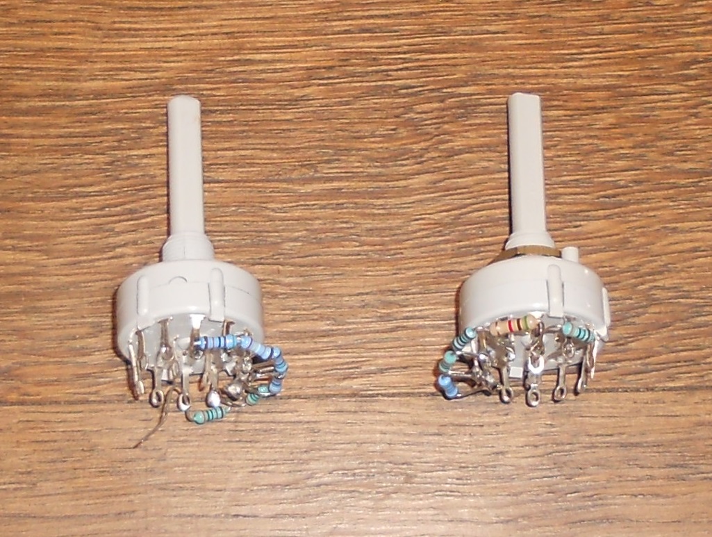
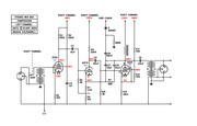
I decided to revert back to the original threshold configuration, but with one addition. I made the original change because I couldn't get any positive pulses from the diode arrangement I had. Then I discovered that you either need a second diode or a resistor, to earth the negative pulses. When I added the resistor the negative supply worked normally. I also changed the signal diode to a rectifier diode because it is possible to exceed the voltage of the original 1N4048 with this circuit. This is the revised circuit.
The Grundig tape recorder schematic I copied, only had a fixed attack and release timing and the threshold control was factory preset. My version with variable timings starts to oscillate with very fast timings so I will have to modify them. Any timing ideas from other users of mix bus compressors will be appreciated.
best
DaveP