You are using an out of date browser. It may not display this or other websites correctly.
You should upgrade or use an alternative browser.
You should upgrade or use an alternative browser.
Mix Bus Compressor from scratch
- Thread starter DaveP
- Start date


Help Support GroupDIY Audio Forum:
This site may earn a commission from merchant affiliate
links, including eBay, Amazon, and others.
Johnny1234
Well-known member
Thanks Dave, you are the man.
I have taken Jacob's advice and it now looks like this:-

I was never happy putting a noisy resistor on the input so this is a much better arrangement.
I have not yet had the time to fully test it yet, but the negative voltage level is identical to the former circuit, so that looks promising!
Thank you Jacob
best
DaveP
I was never happy putting a noisy resistor on the input so this is a much better arrangement.
I have not yet had the time to fully test it yet, but the negative voltage level is identical to the former circuit, so that looks promising!
Thank you Jacob
best
DaveP
Johnny1234
Well-known member
quick question. Will the dc control voltage not saturate the core of the input transformer.
There is no current flowing, impedance at grid is near-infinite
Johnny1234
Well-known member
Ah no current, just potential change.
evil grill
Well-known member
Not wanting to hijack this interesting thread, but what is the process for marking the front panel? I have a compressor that will need text and symbols.I am trying to match the "Ohmite" dials of the input and threshold controls, for the attack and Release switches.
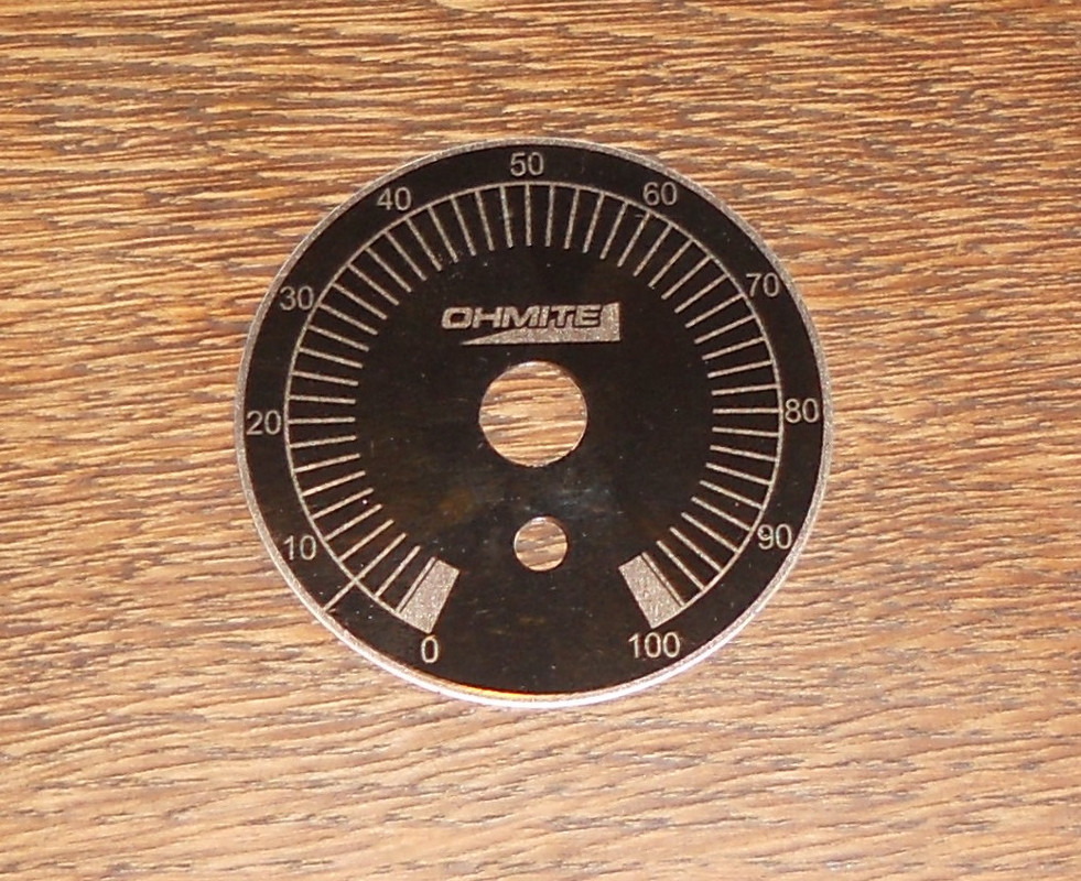
I have produced the dials in MS Paint and will use some cellophane circles to give a durable finish.
best
DaveP
MidnightArrakis
Well-known member
[what is the process for marking the front panel?] -- Depends upon -- how/what -- it is that you want to have this done and/or you would like for it to look. Putting text and symbols onto a front-panel can be accomplish by:what is the process for marking the front panel? I have a compressor that will need text and symbols.
1) Magic-Marker
2) Dymo-Label
3) Silkscreen
4) Engrave (mechanically or by laser) & White-Fill/Black-fill (my preference)
5) Crayon
6) Lipstick
7) Hammer and chisel & white-fill/black-fill
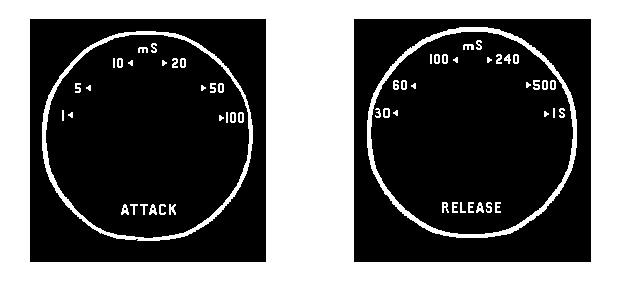
I had designed this rack-panel for its graphics and text to be "engraved & white-filled":

/
I worked out the angles for the switch positions and drew it on MS paint. I printed off copies and enlarged them until I got the size right.what is the process for marking the front panel?
When it was finished, I drew a box around each one and coloured the text red. I was then able to paint the white parts black without losing the text.
Finally, I painted the red text white and printed it off. I carefully cut circles from some thick cellophane, like that you get from a new shirt box.
best
DaveP
ruffrecords
Well-known member
Now THAT is real DIY.I worked out the angles for the switch positions and drew it on MS paint. I printed off copies and enlarged them until I got the size right.
When it was finished, I drew a box around each one and coloured the text red. I was then able to paint the white parts black without losing the text.
Finally, I painted the red text white and printed it off. I carefully cut circles from some thick cellophane, like that you get from a new shirt box.
best
DaveP
Cheers
Ian
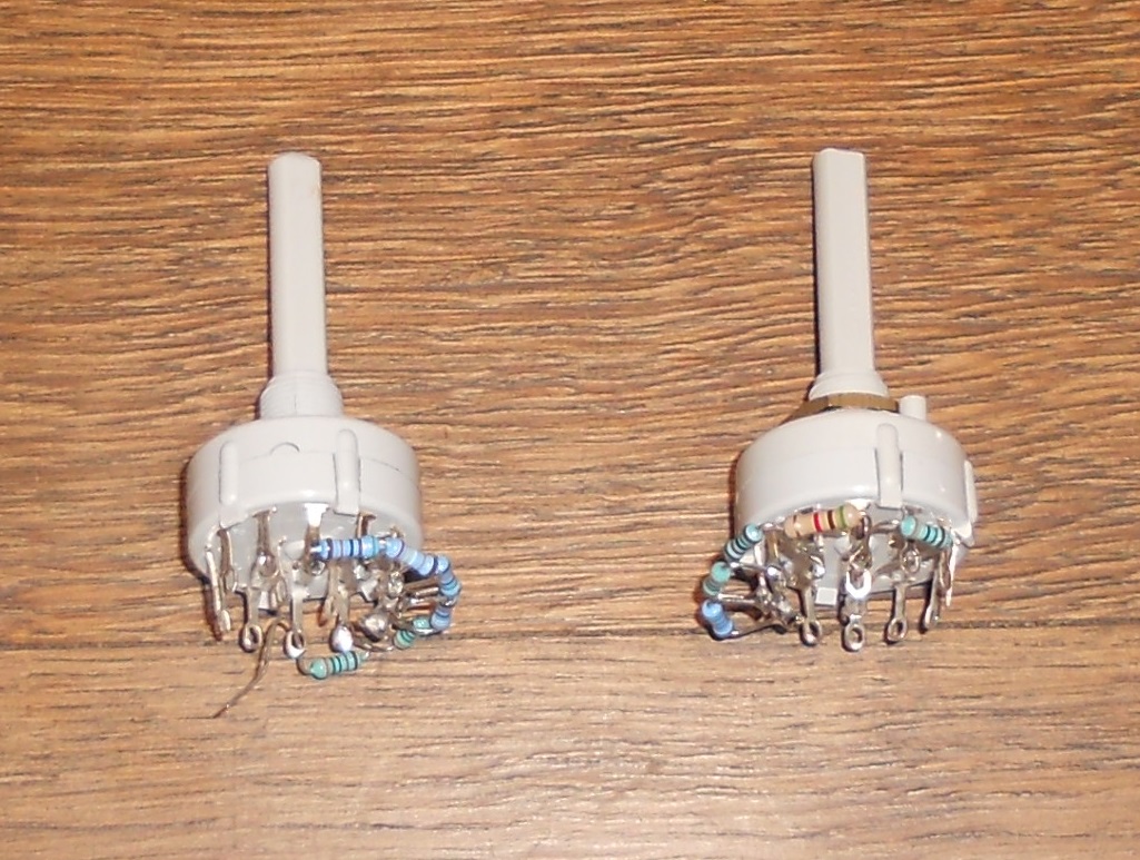
I decided to revert back to the original threshold configuration, but with one addition. I made the original change because I couldn't get any positive pulses from the diode arrangement I had. Then I discovered that you either need a second diode or a resistor, to earth the negative pulses. When I added the resistor the negative supply worked normally. I also changed the signal diode to a rectifier diode because it is possible to exceed the voltage of the original 1N4048 with this circuit. This is the revised circuit.
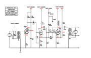
The Grundig tape recorder schematic I copied, only had a fixed attack and release timing and the threshold control was factory preset. My version with variable timings starts to oscillate with very fast timings so I will have to modify them. Any timing ideas from other users of mix bus compressors will be appreciated.
best
DaveP
Last edited:
evil grill
Well-known member
I decided to revert back to the original threshold configuration, but with one addition. I made the original change because I couldn't get any positive pulses from the diode arrangement I had. Then I discovered that you either need a second diode or a resistor, to earth the negative pulses. When I added the resistor the negative supply worked normally. I also changed the signal diode to a rectifier diode because it is possible to exceed the voltage of the original 1N4048 with this circuit. This is the revised circuit.
The Grundig tape recorder schematic I copied, only had a fixed attack and release timing and the threshold control was factory preset. My version with variable timings starts to oscillate with very fast timings so I will have to modify them. Any timing ideas from other users of mix bus compressors will be appreciated.
best
DaveP
https://groupdiy.com/threads/gates-sta-level-recovery-time-mod.10134/
Since my last post I have been testing the design and unfortunately at certain timing settings and input levels there are problems. By a process of elimination I have found that they arise from the input transformers. There are two basic issues, the first is a low frequency pumping like motorboating as the circuit charges and discharges itself. The second is a modulation of the audio signal with an oscillation at 330kHz. At the moment I suspect that this is due to the CV cap and the input transformer being in series resonance. If I make the input unbalanced without the IPT's it cures the problems.
Hi, Ho, onwards and upwards!
best
DaveP
Hi, Ho, onwards and upwards!
best
DaveP
Does this mean you have to find a transformer with a different DCR secondary ?
How do you like the sound when using it unbalanced ?
How do you like the sound when using it unbalanced ?
I have made some progress today. I found out that my use of a 1uF cap on the EF83 g2 grid stopped it working as it should, I swapped it for 220nF as used in the Grundig circuits and it started to reduce the gain. I can make it work if I use the entire Grundig circuit with a 10uF CV cap, but when I start to reduce the timing I get oscillation, work continues.
best
DaveP
best
DaveP
Adolph Ernst
New member
These are the results of my tests on an EF83:
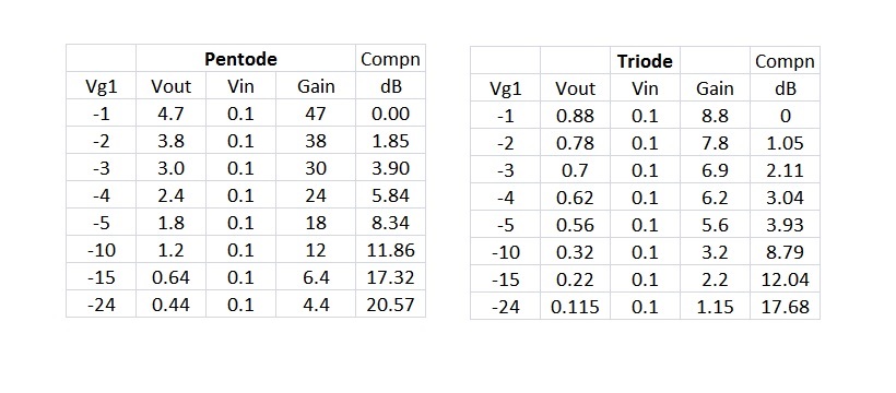
100k resistor on both anodes, 390k for g2 in pentode mode
I would have needed more negative voltage for the triode option and there was the uncertainty about losing the constant current feature of this tube. This is why I stuck with the pentode mode.
best
DaveP
Did you measure anode voltage or current in pentode mode. Did it really stay constant from -1V to -10V grid voltage. I would expect anode current to change if gain is changing, even if the datasheet says different.
I did measure it and the anode current is much more constant than other tubes, but the Grid2 current does reduce a lot. When I originally used an over large G2 cap, it worked against the current drop and stopped the gain reduction.Did you measure anode voltage or current in pentode mode. Did it really stay constant from -1V to -10V grid voltage. I would expect anode current to change if gain is changing, even if the datasheet says different.
best
DaveP
Adolph Ernst
New member
Looks to me your design is going to thump with fast attack and release times and go into motorboating. Even though the anode voltage shift is much smaller than in most tubes the voltage shift is fairly large compared to audio signal. Thump voltage gets fed back in to the sidechain and if there isn't a significant high pass filter it'll start motorboating quite easily.
According to PPR here Grunding had fairly slow attack time and much much slower release.
Attack time slower than 10ms probably keeps the thump inaudible, but still the thump should be kept out of feeding back to the sidechain. If I'm not mistaken some of the commercial tube compressors out there have fastest attack time of 10ms even though those are push pull. 10ms allows for bad tube balance and the customer doesn't complain from audible thumps.
According to PPR here Grunding had fairly slow attack time and much much slower release.
The attack time is around 10mS to 80mS, plus a dozen cycles which adds ~10mS midrange, 100mS bass.
Attack time slower than 10ms probably keeps the thump inaudible, but still the thump should be kept out of feeding back to the sidechain. If I'm not mistaken some of the commercial tube compressors out there have fastest attack time of 10ms even though those are push pull. 10ms allows for bad tube balance and the customer doesn't complain from audible thumps.
This is what I'm working on at the moment Adolph. I have all the Grundig schematics so I can identify the high pass filters. The same CV cathode follower circuit was used throughout the range, but the details of the circuits that fed it were sometimes modified and that includes the filters.Thump voltage gets fed back in to the sidechain and if there isn't a significant high pass filter it'll start motorboating quite easily.
best
DaveP
Similar threads
- Replies
- 3
- Views
- 548
- Replies
- 61
- Views
- 6K
- Replies
- 2
- Views
- 237