Console signal flow, input cards, general discussion on API styled DIY mixer

GroupDIY Audio Forum

Help Support GroupDIY Audio Forum:

This site may earn a commission from merchant affiliate links, including eBay, Amazon, and others.
Thanks for all this Harpo, I really appreciate it, and I'm really glad to be learning how all this works.


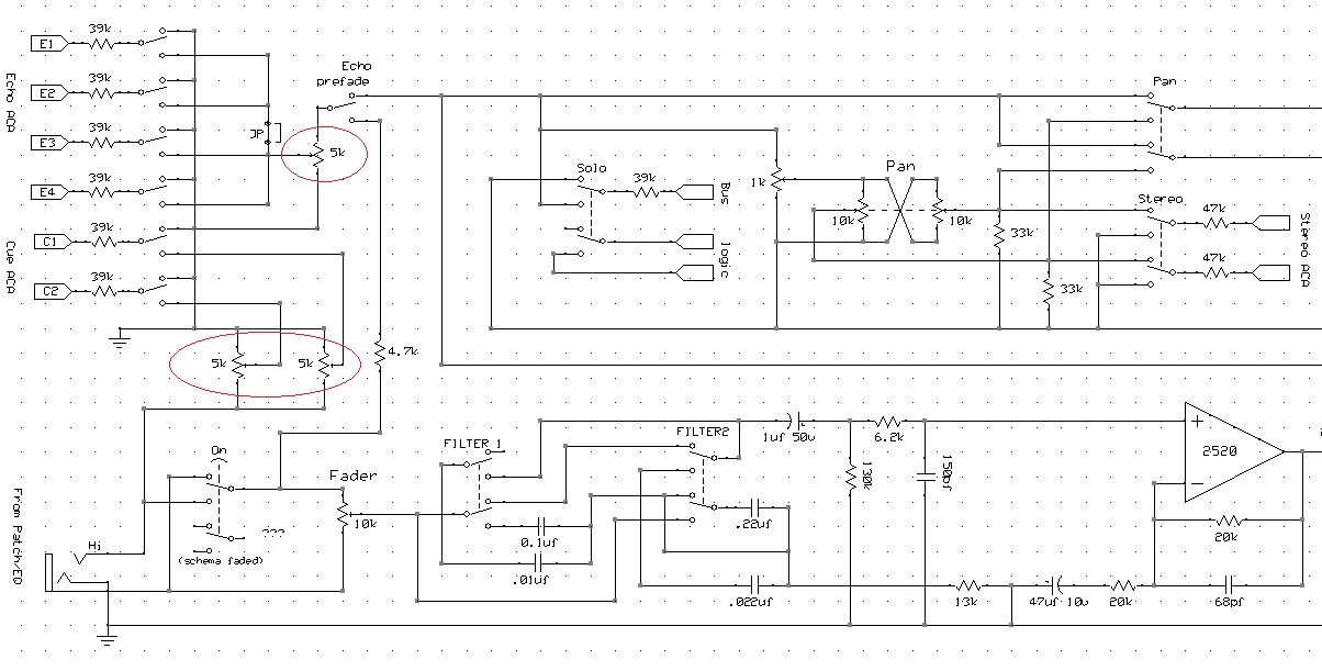
So instead of doubling the cap values and going with the ones Ive calculated to be closer to 2hz-200khz, for "more linear response" assuming I'm going into the standard 2520, do you think these values are ok? the 2520 has a 10 megaohms minimum input resistance.  Could you help me out with the formula to calculate what my input resistance is,..?  If I'm coming from 600ohm transformer to 10k fader etc..? been looking to figureout how to calculate this to see that I'm still in the safe operating area.

soas far as inverting amplifiers , this is how LPF and HPf is calculated to the opamp as a general rule?


yes, meant voltage gain,
well, I'll be coming from a transformer wired 1:2, but I'll be going out unbalanced to a pan and then unbalanced mix buss.. does that leave me 6db short for 12db gain in hand at fader, or am I ok?

thanks again
Harpo said:
Fuccimain said:
If I change the voltage of the 2520 to 2, that will give me 12db "in hand" for the fader correct?
If 'voltage' would be voltage gain and connecting to a 1:2 wired transformer for +6dB iron gain, yes.
 
Fuccimain said:
assuming I'm going into the standard 2520,
whatever a 'standard' 2520 might be. Maybe you're only refering to its 7-pin DOA pinout (one more pin than a similar shaped 990) and assume their OSI to differ by a more or lesser degree.
Could you help me out with the formula to calculate what my input resistance is,..?  If I'm coming from 600ohm transformer to 10k fader etc..?
From your last drawing this transformer would be a 2503 with a 1:1+1+1 winding. Depending on how you hook up this transformer, impedances would change (a transformer reflects impedances by the turns ratio squared, so a separate winding-, parallel- or series-config matters). Reading your previous posts, you still seem undecided between a two windings in parallel or in series config. Additionaly your 'etc..?' would be a lot easier to calculate if you'd put a name and number on it. You are looking for an OSI (optimal source impedance) that fits the opamp/DOA you intend to use. This OSI will be source impedance+(Rfb||Rshunt).

as far as inverting amplifiers , this is how LPF and HPf is calculated to the opamp as a general rule?
yepp for 1st.order R/C filters, assuming low impedance source.
 
Harpo said:
Fuccimain said:
assuming I'm going into the standard 2520,
whatever a 'standard' 2520 might be. Maybe you're only refering to its 7-pin DOA pinout (one more pin than a similar shaped 990) and assume their OSI to differ by a more or lesser degree.
Could you help me out with the formula to calculate what my input resistance is,..?  If I'm coming from 600ohm transformer to 10k fader etc..?
From your last drawing this transformer would be a 2503 with a 1:1+1+1 winding. Depending on how you hook up this transformer, impedances would change (a transformer reflects impedances by the turns ratio squared, so a separate winding-, parallel- or series-config matters). Reading your previous posts, you still seem undecided between a two windings in parallel or in series config. Additionaly your 'etc..?' would be a lot easier to calculate if you'd put a name and number on it. You are looking for an OSI (optimal source impedance) that fits the opamp/DOA you intend to use. This OSI will be source impedance+(Rfb||Rshunt).

Hey as far as "standard", I was referring to the specifications on the API tech sheet for the 2520.

I'm pretty much decided to do 2 secondary windings parallel with 2.2k resistors strapped across them, I put "etc"  cause I didn't want anyone to do the calculations for me, I wanted to learn how to do them myself, and I was assuming there was a formula for calculating the source impedance of the signal from the transformer to the input of the DOA..
So its 15ohm from 1secondary to a 10k fader to a 1uf cap to a 6.2k resistor to the positive input of the DOA.  not sure how the 130k resistor tied to ground and btwn the 1uf and 6.2 affect the source impedance, as well as the 150pf.  the API 325 docs say with 3 windings used for parallel outputs, the output impedance is less than 15ohms.. is that each winding...?

I'm not quite sure how to calculate my source impedance..

I'm trying to learn..
 
so, if I did do 2 secondaries in series to get 6db out of the transformer.. which would be the best way to wire an insert switch?  I've drawn up 2 ways that would cut the signal not being used off the fader, not sure if keeping the insert connected to the fader when insert isn't engaged is going to mess up my source load,.....  to switch between transformer to fader or transformer to insert to fader..I'm still not sure if I need to worry about the "-" or "lo"s of the balanced lines.. as I have drawn,.. switching the hi and lo signals.. as in the larger of the drawings, it's probably overkill and all I need to to is switch the "hi"s and tie all the "lo"s together, as I did in the 2nd smaller drawing on the page...
 

Attachments

  • insert2.JPG
    insert2.JPG
    86.4 KB · Views: 26
ok, so  I updated my fader schematic.  Decided to go out from the transformer 2 secondaries in series for the 6db bump, and have the values for the 1st order HPF & LPF filters updated to be a more linear response.

As far as the insert after the transformer before the fader.. will update once I figure out the best way to implement this, I don't think it would be right  to just send the output from the transformer to both the insert and the fader direct wired..cause the transformer will see both the fader and the insert impedance, and the same thing with the fader.. I don't think it would be right to just connect the output of the insert and the transformer output in parallel to the fader with out a resistor(that I don't know how to calculate) to isolate the signals from each other.. so a switch would be ideal so the output transformer and the fader wont se double loads.

as far as my panner.. need to calculate the value for this.. but as far as the shunt resistor.. I just wire the side of the pot not used to the shunt and the shunt to ground correct?
 

Attachments

  • Fader Booster2.png
    Fader Booster2.png
    47.7 KB · Views: 113
Fuccimain said:
Decided to go out from the transformer 2 secondaries in series for the 6db bump
so transformer wired for ratio 1:2. Reflected impedance is turns ratio squared, so your transformer secondaries want to see a 600 * 2^2 = 2K4 load. This is the parallelled value of the 2K2+2K2 (why two resistors?), 10K, 130K and 6K2+10M, giving 2K985. Should work. The DOA input sees the 6K2 in series to the paralleled values of the 130K, 10K, 2K2+2K2 and reflected impedance of 600 * 0.5^2, giving 6K342. With DOAs feedback network this is an OSI value of 11K342. IIRC the OSI of an API 2520 is about 10K, so you are close.
If your plan would have flodback sends as shown in the API schematic from 1st.page (5K pots in parallel with 39K summing resistors each), these would be in parallel as well, further decreasing the reflected load value.

as far as my panner.. need to calculate the value for this.. but as far as the shunt resistor.. I just wire the side of the pot not used to the shunt and the shunt to ground correct?
Have a look again how API had done it. (Pot wipers go to summing bus resistors, the Rs law benders go between pot wipers and 0V reference voltage).
 
2K2+2K2 (600), 10K, 130K and 6K2+10M= 1/516.595822...  what am i doing wrong?  1/Rtotal = 1/R1 + 1/R2 is the formula i'm using for parallel resistance... 10M is 10 megaohms right?
 
Formula looks right. In your shoes I wouldn't want to know what 1/R total is but R total.
R total=1/(1/(2200+2200)+1/10000+1/130000+1/(6200+10000000))=2984.49579 ohm
There are 2x two series connected resistors (2k2+2k2, hence my 'why two resistors?') and (6K2+10M) in these paralleled ensemble that might confuse you. The 10M DOA input impedance number was from your previous post. Doesn't matter much if this would be 10M or 1M, because total value will be dominated by the lowest resistor values, IE a 1M instead of 10M would decrease previous 2K985 result by 8 ohm.
 
I'm still coming up with a wrong number somewhere. (The 2 resistors to make the 600ohm load was because Abby road suggested that if  using 2 secondaries, to split the 600 ohm load evenly across the secondaries, hence the 2.2 *2)

RTotal= 1/(1/2200+2200)+ 1/10k+1/130000000+1/6200+10000000000)
           

            1/(1/600)
         
            1/.001666666666667) +.0001 + .000007692307692 + 6196.1583
         
          1/ 6196.160074358947
     
          Rt= .000161390278495

Doing something wrong...

I made a mistake and forgot the "1/" before the 6k2 and 10M in the calculation., so with that instead I end up with


RTotal= 1/(1/2200+2200)+ 1/10k+1/130000000+1/6200+10000000000)
           

            1/(1/600) +.0001+ .000007692307692+ 1/6196.1583
         
            1/.001666666666667) +.0001 + .000007692307692 + .000161390324711
         
          =1/ .001935753442239
     
          Rt= 516.595821824....

Still doing something wrong


Fuccimain said:
I'm still coming up with a wrong number somewhere. (The 2 resistors to make the 600ohm load was because Abby road suggested that if  using 2 secondaries, to split the 600 ohm load evenly across the secondaries, hence the 2.2 *2)
...for 1:1 turns ratio connections and he was talking about the paralleled secondary winding and the unused secondary winding. Your last request was for a 1:2 turns ratio to get +6dB iron gain.

RTotal= 1/(1/2200+2200)+ 1/10k+1/130000000+1/6200+10000000000)
...is not what I wrote. Watch the brackets, FI 1/2200+2200 is a lot different from 1/(2200+2200)
Oh, and what does OSI stand for?
same page some posts up...
 
My bad.. They were supposed to be 1.2k resistors across the secondaries..

The transformer wants half the load now that I'm using a 1:2 turns ratio, so it wants to see 1k2, so the point of splitting the load across the secondaries, with a 2k4 on one secondary and a 2k4 on the other should be correct, correct?


My bad on brackets. I'll re do the calculations..

Thanks.
 
I must be doing something totally wrong

1/1/1100+1/10000+1/130000+1/6196.1583

1/.000909090909091+.0001+..000007692307692+.000161390324711

1/.001178173541494=848.77
 
ok so  I think I figured it out the calculations and what I was doing wrong.

one question though,. now that I'm running the transformer secondaries in series, each secondary wants to see a 600r load? i was confused about the turns ratio squared


Harpo said:
Fuccimain said:
Decided to go out from the transformer 2 secondaries in series for the 6db bump
so transformer wired for ratio 1:2. Reflected impedance is turns ratio squared, so your transformer secondaries want to see a 600 * 2^2 = 2K4 load.

I can't tell if what you are saying each secondary wants to see 600 for total parallel resistance of 1k2 or if thats squared for the 2k4,

putting a 1k2 resistor on each secondary gives me a total load of 1k9,  putting a 2k4 on each secondary gives me a load of 2k1, which is closer to the 2k4 you said the transformer wants to see,.. i'm curious why the load the transformer wants to see is  squared: 600 for each secondary, times 2 squared..

im also curious about why the reflected impedance of the transformer is  600 * 0.5^2 when figuring out the OSI for the DOA and why it's  600 * 2^2 when determining the proper load on the transformer ,,,

and how you got to: 11K342 from the OSI of 6K342 via the DOA feedback network...

ok thanks
 
Hello everyone! I know this thread is old as dirt.  I took a break from the console. Ok a huge break..but I'm back at it, and I won't stop now until it's done... sooo... I have a quick question about the 5k pots on the cue and echo's:

I have a crap load of ALPS pots from an Amek Big. Most of them are 20k in various configs- dual gang, dual concentric 20k's being the lion's share.  So my questions are this: Would it be unwise to substitute the API schema's 5k pots for 20k's?  Would it add too much noise, make some of the wiper unusable, or over/underdrive the 2520's?  Also I'd like to be able to make separate aux mixes on all the 'echos' if that's possible, which would mean adding 3 extra pots as well. Thanks for your input!

Also as an aside, I reread everything everyone contributed to this and other threads over the years concerning my foray into console creation. and I've got to say you all have been so incredibly generous with your time and knowledge. Thanks again for helping me figure stuff out -then and now!
-Boji

SfUj3UP.png


qtD5Hwl.png

 
lol, thanks fazer! Well i'm feeling foolish. I really need to buy an audio handbook on design don't I?

cheers
-b
 
Hello yall.  It's been so long I don't even know if I asked this question before and had it answered, but in looking at the 536 schema, I  see API listing COM, AUDIO COM, and GND in the same schematic and just want to confirm the 'COM' being used to move the 16+/- rails is the same as AUDIO COM, which appears connected via ribbon or some such to the right PCB on the Input card. I see no reason why they would be different, I just wanted confirmation to put it out of my mind.  Thanks in advance for your input!

op3HOhL.png
 

Latest posts

Back
Top