Console signal flow, input cards, general discussion on API styled DIY mixer

GroupDIY Audio Forum

Help Support GroupDIY Audio Forum:

This site may earn a commission from merchant affiliate links, including eBay, Amazon, and others.
Hello again, a small update.

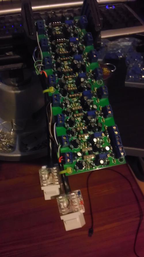
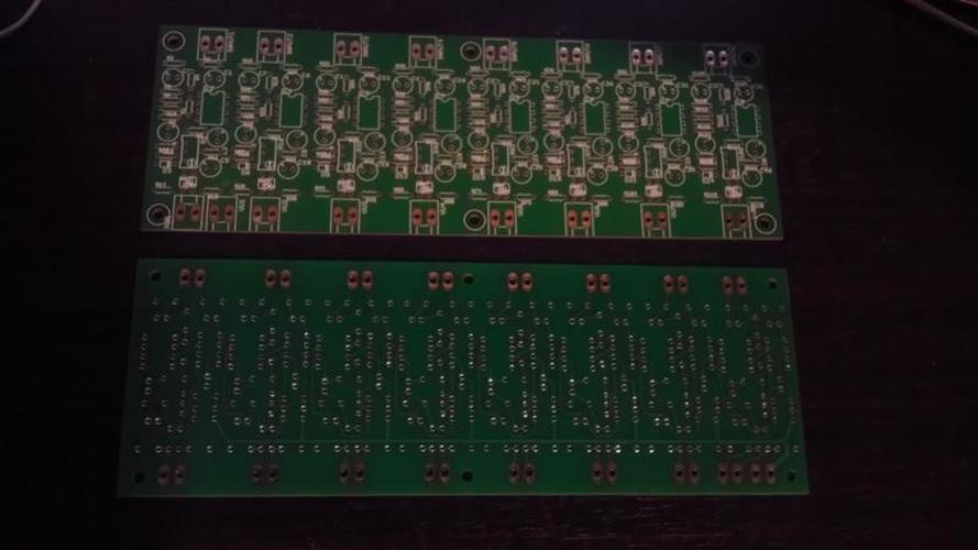
I made some 8 channel VU buffer boards for my console I'm slooooooly building. They are based off of the JLM circuit.

Sorry for the quick crappy photos, I was up all night stuffing one and just finished testing it on a sifam.

Yay, success.  I have a few PCB's left if anyone is thinking of buffering 8/16/24 VU's.

They are fairly compact, ~6.5" x 4".  Honestly the design is meh, the pads are too damn small, the silkscreen is nearly useless, and I did not leave enough spacing btw the pads and gp. But! They work. :)

q86TkIG.jpg


AJu4Xf2.jpg
 
Boji

id be interested in those vu buffer boards!

I'm curious about the drawing for the fader booster.... I'd like to have active fader booster after an API 325 styled input channel.. I know API used 325s as the fader booster sometimes, but what I have drawn has the output transformer going into the fader..(does the LO out from the transformer get grounded like I have done?)  If I've done anything wrong in the circuit, please let me know if you can, I used your drawing as ther basis for "my" fader booster. oh, yeah I want to go out of it unbalanced to a panner I have yet to draw then to 47k buss resistors..

thanks
 

Attachments

  • Screen Shot 2013-06-12 at 12.31.11 PM.png
    Screen Shot 2013-06-12 at 12.31.11 PM.png
    37.8 KB · Views: 92
Fuccimain said:
I know API used 325s as the fader booster sometimes, but what I have drawn has the output transformer going into the fader..(does the LO out from the transformer get grounded like I have done?)
Yes, that's correct. You may want to use a more commonly available 10k fader, then you would have to add a 1or 2 k resistor across it in order to properly load the secondary.
In order to optimise noise, I would use 10k resistors in the NFB path.
 
thx abby road

so I should strap a 1 or 2k resistor across the secondaries of the transformer?  I was thinking of using 2 of the secondaries,. one to feed an insert send, the other to go to the fader if no insert was used.., I should strap a loading resistor across both of the secondaries, cause each secondary wants to see 600ohm correct?

as far as the 10k resistors in the non feedback path.. i'm a little confused.. your saying on the positive input to the 2520, I should change the 6.2k or do you mean somehting else?

thanks again
 
Fuccimain said:
so I should strap a 1 or 2k resistor across the secondaries of the transformer?  I was thinking of using 2 of the secondaries,. one to feed an insert send, the other to go to the fader if no insert was used.., I should strap a loading resistor across both of the secondaries, cause each secondary wants to see 600ohm correct?
No. The transformer wants to see a combination that's equivalent to 600 ohms; that could be 2x 1.2k, or one 600 ohms and nothing, or 10k on one secondary and 640 ohms on the other. But this is just theory, you can deviate as much as +100% without any ill effect. Anyway any perfect calculation will be confronted to reality (different load impedance, variations due to fader position,...)
as far as the 10k resistors in the non feedback path.. i'm a little confused.. your saying on the positive input to the 2520, I should change the 6.2k or do you mean somehting else?
NFB means Negative FeedBack. I mean the 20k resistors that go to the negative input.
 
I got you. Although I see how 2 1.2k resistors (one on each secondary) Makes 600ohms, I don't see how a 10k and a 640 come to 600..  Unless you are talking about the 10k fader.. Just a little confused on that.

As far as the nfb resistor becoming 10k, can you explain why 10k is better ? I believe you I'm just curious and would like to know why it's better for noise than the 20k

Thanks!
 
i found the parallel resistance formula so I figured out the 10k 640... .. curious if the !0k fader will be loading the transformer though..  so should I be loading the transformer to 600 ohms with a 640 resistor to get it to 600ohms with a 10k fader in parallel?
 
Fuccimain said:
i found the parallel resistance formula so I figured out the 10k 640... .. curious if the !0k fader will be loading the transformer though..  so should I be loading the transformer to 600 ohms with a 640 resistor to get it to 600ohms with a 10k fader in parallel?
You could, but it wouldn't be the best "match". I would tend to favour similar loads on both windings, and considering that I think it's stupid to load the 2520 at max load for no good reason, I would put a 2.2k resistor on each secondary. In combination with the 10k fader on one side, and the hypothetic and unknown load on the other side, that would be equivalent to about 1k load, which is about 60% of the 2520 capacity. Remember that, if you load the "other" output with a 600 ohms load, the transformer will be overdamped, thus impairing HF response, and the 2520 will have a hard time driving the total load. Multing from a single output has its limitations.
 
That makes sense. You think I should tie both secondary lows together with the insert return low and just use a spdt switch, or use a 4dpt like I made in this drawing to keep the -'s separate...

Also, Abby road, I made a thread in the lab section about a mixer I having a couple issues with, if appreciate any input you could help me out with.. Nobody has replied to it yet and I for one can't figure out the feedback resistor value for starters...

http://www.groupdiy.com/index.php?topic=52747.0
 

Attachments

  • image.jpg
    image.jpg
    263.8 KB · Views: 32
Oh also, if I do change the feedback resistor to 10k, it's going to increase the gain of the 2520? Is that how it optimizes noise?
 
Fuccimain said:
Oh also, if I do change the feedback resistor to 10k, it's going to increase the gain of the 2520? Is that how it optimizes noise?
If you change both resistors, gain will be unchanged. However the impedance seen by the negative (inverting) input will be halved, which is good for noise performance.
 
Fuccimain said:
That makes sense. You think I should tie both secondary lows together with the insert return low and just use a spdt switch, or use a 4dpt like I made in this drawing to keep the -'s separate...
Too complicated. First, do you really want an insert switch? It's useful only if you want to bring an effect on or off, if the outboard doesn't have a bypass switch (or it's located too far).
Anyway, you don't need two secondaries to run inserts. You mentioned you wanted the second winding for direct output. In that case, use it just for that.
 
Don't need a direct out. Only want to be able to insert a processor before the fader, is it too complicated cause my switch design is not accurate and missing something or should I have just gone with a 2dpt switch for the "+"s and tied all the "-"s together....?

I also thought about using the 3rd secondary windin to feed a vu meter buffer...
 
Fuccimain said:
Don't need a direct out. Only want to be able to insert a processor before the fader, is it too complicated cause my switch design is not accurate and missing something or should I have just gone with a 2dpt switch for the "+"s and tied all the "-"s together....?

I also thought about using the 3rd secondary windin to feed a vu meter buffer...
A DPDT switch is all you need. You may want to parallel two of the windings for feeding the fader. Use the remaining to feed your meter buffer.
 
I'm trying to visualize running 2 secondaries in parallel to the fader . Just tie both hot and cold points from the transformers 1st 2 secondaries to the same points on the fader? Essentially just linking 10&12 and 11&13 together to the fader? I wouldn't  see 6db increase like running 2 secondaries in series right?  Trying to see what the advantage is of doin this and how to apply an insert if 2 secondaries are in parallel To fader.. Guess I'm uncertain why to do like that over 2 secondaries split to fader and insert separately..
 

Attachments

  • image.jpg
    image.jpg
    197.5 KB · Views: 10
I guess what I drew in my switch drawing was a dpdt switch.. Not a 4dpt..

So that should work,

I guess this image is what you meant? Little bit confused about secondary in parallel
 

Attachments

  • image.jpg
    image.jpg
    409.5 KB · Views: 11
Fuccimain said:
I guess what I drew in my switch drawing was a dpdt switch.. Not a 4dpt..

So that should work,

I guess this image is what you meant? Little bit confused about secondary in parallel
Yes, that is correct.
Now about the 6dB that the transformer may give, if you ran the secondaries in series instead of parallels, this is something that should be decided upon drawing a proper level diagram. Do you really need +4 dBu nominal level with 20 dB headroom at the insert point, or are you content with -2dBu nominal?
I can't answer that for you. It depends on your choice of outboard mainly.
Many console manufacturers have opted for the latter configuration.
If you run the secondaries in parallels, you may want to increase the fader buffer gain by 6dB, in order to still have the 10-12 dB in hand at nominal position.
 
honestly I'm content to do whatever sounds the best 1st, and 2nd, whichever is easiest to implement.  How was it done on vintage consoles? API 1604s come to mind.

One thing that comes to mind is if I use 2 secondaries in series, with the +6 db bump, the 3rd secondary to feed the meter will be -6db lower...

Will how I use the input side of the channel be a determining factor in this? as i haven't discussed the input concept, and wether I should allow the transformer to give the +6.

I'd like the input channels to be able to run at unity and be able to pad down a couple steps and go above.  if I don't get the +6 from the transformer, the 325 can run at unity, I was thinking of having a T-pad in front of the input, maybe down 6 or 7 db since the gain of the 325 is 40db (without transformer), if I divide 40db by 12 steps (12 pos attenuator) it's roughly 3.333db per step in gain.  I was thinking 2 steps below unity, then the rest from unity to max which would be +33db.(40db total)  plus whatever the transformer is going to give 0, 6 or 9.

I've looked everywhere to find how to calculate what resistor values to use between 7 and 8 of the 325, The 8 page 325 pdf on the classic api site http://www.classicapi.com/catalog/images/reference_docs/325-docs.pdf only gives formulas for differential and lossless combining usage of the 325, not for the line amplifier application I read somewhere that the total resistance btwn 7&8 is 47k (because the FB resistor is 47k?) and that using the total resistance, the maximum gain(of amp without xfrmr) and how may steps can provide resistor values.. i found this calculator on the web and I'm curious if those resistor values look correct in the image.

If my T-pad idea isn't a dumb one, for reasons I haven't realized, I'm leaning that way,.. no whether the transformer should be used to makeup the level that I lost in the T-pad..... so many choices
 

Attachments

  • gain stage.png
    gain stage.png
    55.1 KB · Views: 26
Thanks for that. I'll have a better brain to process that in the morning win some coffee..

Thanks again
 
Back
Top