You are using an out of date browser. It may not display this or other websites correctly.
You should upgrade or use an alternative browser.
You should upgrade or use an alternative browser.
Starting a modular console - CAPI/GDIY 508 rack build
- Thread starter Krcwell
- Start date


Help Support GroupDIY Audio Forum:
This site may earn a commission from merchant affiliate
links, including eBay, Amazon, and others.

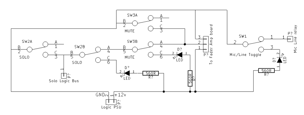
I did some work on my schematic this morning based on a separate 12v Logic PSU for relays and LED's. I also added the mic/line toggle section, which will be controlling a CAPI relay board further up the signal chain, and the mute/solo switch logic for the CAPI relay board pictured in the schem.
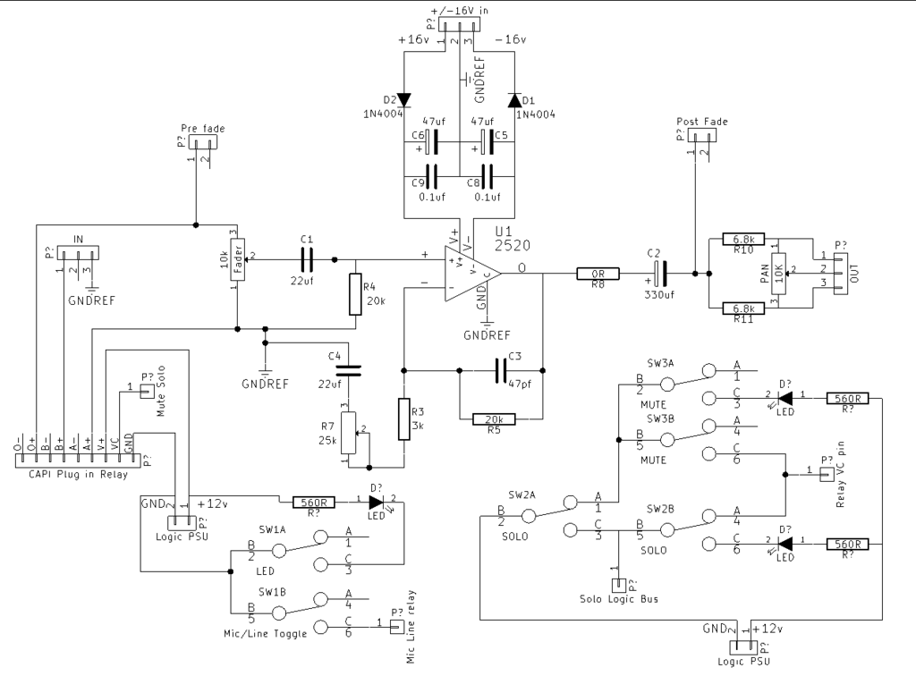
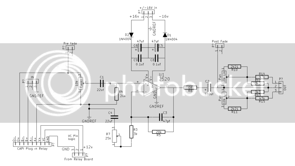
I'm going to update the pan section for a dual 10k linear based on a schematic Jeff posted in his white market thread the other day.
Hopefully I'll find some time to breadboard this circuit out in the next day or two for some testing. In the meantime, please let me know if you see any problems with this schematic. I'm still not quite sure what I'm doing, but things are starting to make a lot more sense.
Edited: after walking away from it for a couple hours, I realized the flaw in the mute/solo switching logic above. Mute would send the GND signal to the solo logic bus.
Here's potential fix #1. Ignore R5 and C3 in the upper left; they got caught in the screenshot.

I've been doing some more thinking on power supply as well.
Refresher:
1) I want to add a 12v logic power supply for relays, led's, etc... probably meter lights as well, I'm assuming?
2) I currently have a GDIY Floorbox PSU from CAPI, which will easily be able to meet my power needs in the near term, with half of it powering the summing section's ~40 2520's, the other half powering modules. However, I'm going to outgrow it sooner than later, so might as well think about it now.
After some searching, I came across this thread, which had some very good info on other people's solutions for a console power supply.
http://groupdiy.com/index.php?topic=52316.0
I really like the idea of using pre-made linear power supplies, especially since the amperage is starting to get out of "DIY kit with easy instructions" level.
Looking at the International Power Open Frame line, I've compiled the following hypothetical power supply that should fit into a 3u 14" deep rack case.
2 x 15V 6A http://www.galco.com/buy/International-Power/IHD15-6.0
Wired as described in the thread linked earlier, these would provide +/-16v rails with 6A. It appears that these PSU's can easily be adjusted to 16v, but I need to do some more research on that.
1 x 48V 0.5A http://www.galco.com/buy/International-Power/IHB48-0.5
For phantom power. Should be more than I ever need.
1 x 12v 1.7A http://www.galco.com/buy/International-Power/IHB12-1.7
For relays, LED's, meter lights, etc...
Just initial thoughts for the time being and, as with most things, more research is needed on my part. Any feedback is appreciated!
Thanks.
Keith
gar381
Well-known member
Prebuilt manufactured supplies are a great way to go and
Can be a great cost savings over higher amperage DIY supplies .
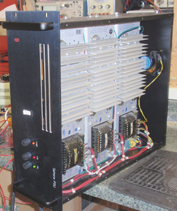
I ebayed these 3 13 Amp "Power One" used supplies at $38 each.
for my Sphere Sidecar and they work great.
Shop around Keith")
GARY
Can be a great cost savings over higher amperage DIY supplies .
I ebayed these 3 13 Amp "Power One" used supplies at $38 each.
for my Sphere Sidecar and they work great.
Shop around Keith
GARY
Amazing work you are doing,
will follow your thread with great interest.
Have a good work!
will follow your thread with great interest.
Have a good work!

Very cool! I am thinking to make a mixer myself, altough a simpler approach.
I am wondering on something though:
I have no real clue on this, but wouldn`t it be better to have the mute after fader? Is there any special reason it is placed earlier in the signal path? School a newb please
I am wondering on something though:
Krcwell said:

I have no real clue on this, but wouldn`t it be better to have the mute after fader? Is there any special reason it is placed earlier in the signal path? School a newb please
gar381
Well-known member
fragietrollet
In this drawing the pre fade out is also muted.
GARY
In this drawing the pre fade out is also muted.
GARY
totoxraymond
Well-known member
Hi,
Pre-fader mute is usual signal path for most desks. Some bigger desks offer a possibility to leave pre-fader outs "unmuted" with internal jumpers. (Allen&Heath designs for example).
Your work here is amazing.
Thomas
Pre-fader mute is usual signal path for most desks. Some bigger desks offer a possibility to leave pre-fader outs "unmuted" with internal jumpers. (Allen&Heath designs for example).
Your work here is amazing.
Thomas
Thanks for the answers. I was just thinking that by muting later in the signal path you would lower the noise coming from the (muted) channel, not having all those gainstages running. I do understand it is implemented the way it is in this case because of the pcb`s being used, but what is the design-reason of having the mute that "early"?
totoxraymond
Well-known member
If The mute is placed before the pre-fader signal, muting the channel includes muting all pre-fader sends. So the signal is cut for every outputs. If you place it post-fader, you would only cut the signal feeding post-fader sends and main buses.
Right! I guess it would be nice with a switch for choosing pre/post muting 8)
My only plan for the time being is to run the pre and post sends to the meter switch and meter. At some point much further down the road I will hopefully build in aux's and what not. That will be the Mark II version. MUCH further down the road.
I've done more work on the schematic, separating it into the 2 pcb's - mute/solo pcb & fader amp pcb. These will be stacked on standoffs to populate the frontpanel idea I posted a bit back.
I'm pretty much ready to start turning these schems into pcb layouts, but I would really appreciate as many eyes as possible to point out possible flaws before I start trying to work up a layout.
The fader amp board:
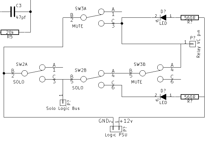
The Mute/Solo/Relay control board (Refresher: ground to VC pin = mute):
Edit: removed. Saw the problem in the logic. Fixing it.
Edited again: Nah, let's make this fun. First person to point out the flaw in the below schem wins a brand new xicon 10k resistor, mailed by the cheapest means possible.
Much appreciated,
Keith.
I'm pretty much ready to start turning these schems into pcb layouts, but I would really appreciate as many eyes as possible to point out possible flaws before I start trying to work up a layout.
The fader amp board:

The Mute/Solo/Relay control board (Refresher: ground to VC pin = mute):
Edit: removed. Saw the problem in the logic. Fixing it.
Edited again: Nah, let's make this fun. First person to point out the flaw in the below schem wins a brand new xicon 10k resistor, mailed by the cheapest means possible.

Much appreciated,
Keith.
totoxraymond
Well-known member
Hi Keith,
It seems that the problem is around Sw3 in serial with with Sw2. In this drawing D? will never light up. Plus you will send the signal to solo bus by muting the channel.
Also, i don't understand why u had the pin 4 of Sw3 connected to VC.
Am i right?
Thomas
It seems that the problem is around Sw3 in serial with with Sw2. In this drawing D? will never light up. Plus you will send the signal to solo bus by muting the channel.
Also, i don't understand why u had the pin 4 of Sw3 connected to VC.
Am i right?
Thomas
totoxraymond said:Hi Keith,
It seems that the problem is around Sw3 in serial with with Sw2. In this drawing D? will never light up. Plus you will send the signal to solo bus by muting the channel.
Also, i don't understand why u had the pin 4 of Sw3 connected to VC.
Am i right?
Thomas
We have a winner! Please PM me your address and I will send out your fabulous prize!
The issue was the LED. Mute shouldn't make it's way into the solo logic bus as both 3A and 3B would flip at the same time, connecting ground to VC pin and disconnecting the solo logic bus from the chain.
Pin 4 of switch 3 is there to send the solo logic bus signal to VC pin. If another channel gets solo'd, then ground is connected to the solo logic bus which then feeds in to VC pin of all other channels that are not solo'd. Switch 2 connects the solo logic bus to ground and then disconnects the logic bus from that channel's VC pin. This can then be overridden with the mute switch to mute a solo'd channel.
My thought is to just connect the mute LED that currently goes nowhere to the last segment going to the VC pin. This way, if for any reason ground is going to the VC pin, muting the channel, the mute LED would light. This would either be caused by the channels mute switch being activated or another channel being solo'd.
Hopefully that all makes sense. I'll post an updated schem when I get home from work today.

totoxraymond
Well-known member
Well it should work better this way, but I would not make it this way.
As i understood, if you solo a channel it will just mute all other channels rather than route the soloed channel to a solo bus.
This means that you can't use solo anytime you want.
i.e. if you want to listen to a particular channel in the middle of a recording, it would 'kill' every other channel and therefore ruin your recording. I don't know what are the applications for your console, but in my opinion, such a design will be a problem some day.
If i had to do this kind of work, i would route soloed track to a different bus and make sure that this bus override master out (SIP) or just route to monitor output. This way you're sure that no track would be cut either for buss routing, direct out, or sends.
In the end, it's just my feelings, you may have lots of reason to do it your way.
Thomas
P.S: I actually live in Paris (the one in France, not Paris TX) so it would a very long trip for a tiny resistor.
Thomas,
Well, if you ever find yourself short one 10k resistor, the offer still stands! I don't want people to think that I back out of commitments...
I did a lot of looking around when thinking about the mute/solo operation, and decided to go with the "destructive" solo method as it fits how I plan to use it, as you said. The project is much more a DAW front end with a stereo bus/summing amp than a true console. Here's a general signal flow diagram:
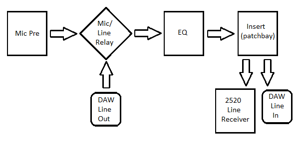
The to tape/DAW for each channel will be a mult of the post-eq insert output, so it will feed into the DAW inputs separate of the summing stage, which contains the mute/solo logic. I'll use the DAW for headphone cue mixes, so mute and solo really only effect control room monitoring/playback for tracking and mixdown.
I really appreciate the insight, keep it coming! Like I've said before, there will eventually be a Mark II version of this, and these are all great ideas to incorporate into that. My project timeline is: 1) finish Mark I version -> 2) fill out the mic pre, eq and compressor slots -> 3) begin work on Mark II console section. I think that #2 will take a while; I need to buy and build 6 more pre's and 10 more eq's, just not sure where that $4-5k is going to come from yet...
Keith
Similar threads
- Replies
- 4
- Views
- 313
- Replies
- 44
- Views
- 3K
Latest posts
-
 Built custom channel for Soundcraft Boards (SSL like)
- Latest: MidnightArrakis
-
-
-

-