A new take on the GSSL (Pics Inside)

GroupDIY Audio Forum

Help Support GroupDIY Audio Forum:

This site may earn a commission from merchant affiliate links, including eBay, Amazon, and others.
[quote author="mathflan"]like radiance, I have relay circuit, a power led and a Led for the bypass.

Matt or mnat, is it possible to have the schematic of this PSU.
:wink:


matt , so you use 317 and 337 Regulator or you have keep 78L15 and 79L15.[/quote]


I don't have the schematic, I just had a board lying here and so used it, it could have been ANY spare PSU, but it was MNATS as I had one handy and it is a joy to work with.

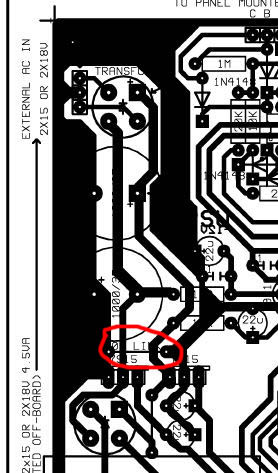
And yes you need adjustable regs, an LM317 and LM337 for his PSU to work.

Cheers

Matt
 
Perhaps to decrease the SSL humming one could try increasing the values of the onboard PSU capacitors instead?

Could be, I just took the 'EASY' way out in the sense that it was easier to just build a new, trimable PSU and feed the comp and meter with it. I think you could also add some bypass caps on the output filter caps? I didn't try it...

One thing about GSSL is that there are a couple ground loops on the PCB, not that they have a MAJOR effect on the board, but one place I did find it helped alot was to remove the jumper just behind the voltage regs.

If you look at the PCB even without the jumper the ground plan still extends to that region, by jumpering it you are creating a loop around the entire board.

I don't think traces have to be cut and adjusted to still get it to sound great and be low noise, I'm MORE than happy with where I am at now with my GSSL and the samples shwo the difference, they are exact A/B's before and after the PSU adjustments.

Cheers

Matt
 
matt you 're right, there is a ground loop :

Groundloop.jpg


Maybe it's volunteer from gyraf...

If this schematic of a PSU with LM317 and LM337 is appropriate for SSL :

http://www.sonelec-musique.com/images/electronique_alim_symetrique_001.gif
 
If this schematic of a PSU with LM317 and LM337 is appropriate for SSL :

Yes, it would work, you would just need to work out the strapping resistors to get the correct voltage. Those input filter caps are SERIOUS at 2200uF per rail, on the GSSL it is spec'd at 1000uF, and that is what I have on my PSU and it works fine.

There are quite a few PCB layout for various PSU's here with a lot of research, why not etch one yourself, I mean the Peter C, Keef's SSL9K PSU as well as TK's PSU would all fit the bill with the appropriate changes (none on Peter C's since it is speced for dual 15V rail, and you could just leave the 48V part unstuffed.)

No need to reinvent the wheel... do a search here for options.

Cheers

Matt
 
Matt or mnat, is it possible to have the schematic of this PSU.

mathflan, I can really recommend the JLM AC/DC PSU board, if you are looking for an off board PSU. You can also pull 48V for relays off of that. It is not expensive and works great!
 
[quote author="matta"]
I will in time post drawings of the mod... again I can't take credit for it, it Neeno's hard work that prevailed!
[/quote]
Matt - I am a lazy sod - so I await your drawings
Love the back panel (front's nice - but the back - very neat)
 
[quote author="martthie_08"]
Matt or mnat, is it possible to have the schematic of this PSU.

mathflan, I can really recommend the JLM AC/DC PSU board, if you are looking for an off board PSU. You can also pull 48V for relays off of that. It is not expensive and works great![/quote]
Or 24 V like I did (converted the slow 48V to a normal +24 - or you could drop it a 12 and have a clean 12 for the relays)
 
I Added the JLM AC/DC PSU with two Rails and Added another rail with a LM317 :

http://www.jlmaudio.com/JLM Power Station.pdf

But It seems that My SSL is now Very sensitive to Electromagnetic Source.

Matta Is it possible that you Describe me the Wiring of the Grounding on your SSL.
I'm a little lost with the Ground since I added this PSU.

I use
a Relay circuit.
a Bypass Switch with LED
a sidechain Circuit.

My XLR Sockets are connected to the RACK by the screws.

thanks for help
 
Matta Is it possible that you Describe me the Wiring of the Grounding on your SSL. I'm a little lost with the Ground since I added this PSU.

Hey Mathflan,

My ground scheme is a star ground scheme and works as follows.

IEC Earth is mounted to the Star Ground
Seperate wires from Input XLR's Pin 1's to Star Ground.
OV from the Main PCB to Star Ground
OV from PSU to Star Ground

NO Ground wires on the OUTPUT XLR's to Star Ground

And the unit is SILENT, no hums from grounding or EM problems.

Hope that helps.

Cheers

Matt
 
Thanks matta. :grin:

I Find my ground loops.

I Had a Ground loops with thre Relay circuit and I Forgot to Connected the 0V from main PCB to star ground :oops: .

Just one thing, YOu said "NO Ground wires on the OUTPUT's " but You means that Pin 1 and XLR's plugs are not connected to the Ground? You have just connected the XLR's plugs to the chassis...Thats' right.

In fact I did that :

SSL-Grounding.jpg
 
Hey Mathflan,

I have corrected my post above.

Based on your drawing your don't have a proper Star Ground Scheme.

Take a look at your PSU's, you are referencing the Star Ground AND your PSU Ground. Your 0V on the PSU should go to the Star Ground NOT the Main PCB and Relay Board.

Take a seperate wire from the PSU 0V outs of the PSU's to the Star Ground and from the Star Ground take a wire to the Main PCB 0V and Relay Board.

REMOVE the GND INPUTS wire you have there, it isn't needed.

Also on the INPUT XLR's I have a seperate wire running to the Star Ground on Pin1.

I don't think you need the wire from the Star Ground to the AC input of the PSU as you have it drawn.

Regards

Matt
 
Ok thanks matta, so I have to wire :

0 Volt PSU to star ground.
0 V Main board to star ground.
0 V Relay board to star ground.

But On The JLM PSU :

JLMACDCwiring.jpg


it's note that I have to wire The Ground to the Metal chassis so to the star ground.
Is it important here?
 
On the JLM supply if you wire it that way it shows above the output 0V becomes the Star Ground point.

There is continuity between the Ground on the Chassis through a METAL (conductive) stand off and 0V on the output of the PSU, with a 10R straped across it.

Where I have indicated 'Star Ground' that would now be the output 0V on the JLM supply.

Does that make sense?

The 0V wire to the PSU is important as it needs to be Star Grounded or else you may end up with a differential ground plane.

Cheers

Matt
 
I made the star ground and My SSL is now "Muet comme une carpe" French expression :grin:

I don't Have Noise Anymore, very clean.

Thanks matta and JLM audio.
 
Matta, is that "round steel toroid fixing thingy" or the bolt touching the top plate of your ssl? If so, put some insulation on top because it can be very dangerous.
 
Matta, is that "round steel toroid fixing thingy" or the bolt touching the top plate of your ssl? If so, put some insulation on top because it can be very dangerous.

Hey Radiance,

Thanks for the concern, but nope it isn't touching there is around 3-5mm clearance between the plate/bolt and the top of the case.

Cheers

Matt
 
Uff i just saw it- GREAT. like it a LOT... and thanks on all the good info you've provided...

cheerz

m
 
Back
Top