Active Ribbon Preamp/Impedance Converter Idea - opinions?

GroupDIY Audio Forum

Help Support GroupDIY Audio Forum:

This site may earn a commission from merchant affiliate links, including eBay, Amazon, and others.
Yes, it's noise + shell. German has "das Rauschen" = noise and "der Rausch" = intoxication. In word formation affixes can be lost, so "Rauschen" is clipped to "Rausch". Languages just do stuff without much logic. But you figured it out, nonetheless. So, yes, it's a mic test device. It acutally looks quite a bit like a bomb. I recently phoned with a guy who writes for another magazine. He's a measurement technician (Messtechniker) in real life. And of course he built his own "Rauschbombe" (among other, much weirder devices). So if I really get the time to build one myself, I guess I'll just call him :wink:

So I could acutally recuce R2 and R4 a bit? Some quite respected microphones are actually impedance balanced. The TLM 103, to name just one. The Oktava 012 preamp, too, is impedance balanced (for whatever reason using two different sized resistors of 51 and 39 ohms). Both seem to work just fine under real world conditions. So if there's nothing else wrong with my circuit, I guess it should work okay. Where's my soldering iron? :grin:
 
[quote author="Rossi"]

What about this:

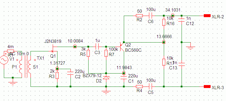
aribimpbal.gif


This is (supposed to be) an impedance balanced version with just one driven line. Would this behave better?[/quote]

I agree with PRR that single-ended especially with low Z overall is often fine. Pseudo-balanced like you show is a good expedient when you consider other issues and want to keep things simple.

However, as drawn the output PNP has little room to swing voltage, as the base-collector voltage is about zero except for the drop due to the base current of about 14uA (assuming a beta of 300) across R7. But even that will serve for a lot of signals, so just be aware that it will limit negative excursions. An additional R between base and emitter could pull things up a bit and give more room to swing, without going to the extremes of the big-Vbe-multipliers of the output stage I suggested.

For balanced impedances you should also take the naked emitter Z into account, which at 4mA of emitter current is pretty small (maybe 7 ohms or so), so again not a big effect. [EDIT: and I neglected the effect of the impedance from the FET stage at the base, which appears reduces by a factor of beta at a given freq at the emitter, so this adds some more ohms. Maybe R2 36 ohms and R4 50?] If you are really anticipating a lot of abuse you could put a reverse-biased diode across Q2 B-E as well.
 
[quote author="Rossi"]What about this:

aribimpbal.gif


This is (supposed to be) an impedance balanced version with just one driven line. Would this behave better?[/quote]
Hmm, starts making me think of this one (yet again :cool: ):

http://www.jensentransformers.com/as/as004.pdf

Note that it's a 10kOhm-TX there (T1); the FET+PNP-circuit might need some heavier biasing to be able to drive a mic-input.

Regards,

Peter
 
Thanks again PRR and Brad! :thumb: :thumb:

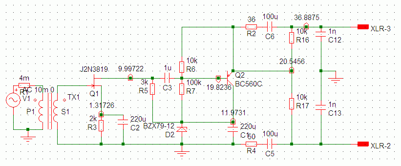
So here's the revised version with Brad's suggestions incorporated:

aribimpbal2.gif


Looks good in sim, FET gain is about 14.5 dB, which should be about right as this single ended version has no addional gain from the output stage. Ready for real world testing. :grin:

@ Peter: Yeah, the Jensen schematic looks kinda similar. Which is perhaps not surprising; a guitar pick-up isn't so different, except that its impedance is usually a good deal higher than even the "overwound" transformer ribbon mic's.
 
> for whatever reason using two different sized resistors of 51 and 39 ohms

One side is hard ground, very nearly zero impedance. The other side is Amplifier Output. Even a low-Z amplifier never has zero output impedance. As bcarso shows, for simple amps this may be 7 to 17 ohms. Apparently Oktava's designer thought his plan was close enough to 12 ohms to use 51 and 39.

> might need some heavier biasing to be able to drive a mic-input.

The Jensen takes guitar pickup signals, which can be 1V peak (it claims to accept 5V peak).

If we have 1V out of Rossi's booster, we don't need a booster at all.

Jensen is designing for worst-case hot guitar. Rossi is boosting too-weak signals.

What can we get from the "What about this?" plan?

As bcarso says, only 1V or 2V peak as shown. We could "improve" that, but again if we have 1V boosted, we maybe don't need a booster at all. The problem is when we have 1mV unboosted, and the board gain or noise would rather have 10mV.

Q2 appears to be flowing 4mA. If we put ALL of that to a load, THD would be high. Say we can take 1mA peak without great distress. We can put 1V and 1mA into a 1K load, which is roughly a board input. Even 100 feet 30m of cable is not very upsetting. Even the new-new revision with ~3mA doesn't upset things enough to hurt. Since the booster can be removed(?) for high-level sources, and will mostly work below 100mV, it should be quite ample.

If you put a hot capsule on a guitar amp and run 1,000 feet cable, yes, you need considerable muscle in the line driver. If you have True 150 Ohm inputs, then you need some beef for levels over ~100mV. As I understand Rossi's goal, he's on the other end of the street.
 
[quote author="Rossi"]As I said, this circuit is meant for an article on ribbon mic modifications (in a musicians mag).[/quote]
Already known in which issue (month) it'll appear ?

Cheers,

Peter
 
Sorry, I forgot to make an announcement. The article got divided into two parts. The first part is in the current issue (which appeared about a week ago) and is about rbbon mic technology in general and transformer replacements (Lundahl, Edcor). It is 5 pages + some (simple) audio files for comparison on the cover CD.

The second part is goin to be more intesting for DIYers, I think. Among other things, there will be a tutorial on re-winding the stock transformer as an active ribbon transformer, a simple impedance converter circuit (no extra gain) and PRR's ribbon booster circuit from the "old" active ribbon thread. Actually, it'll be a new version comprising fewer parts (at the sacrifice of having to match a few resistors.) The main reason for the new revision, which PRR came up with, is that it draws better without crossing lines. So it looks less confusing for beginners. The acutal performance is identical to the "old" version.

The second part is bound to be 7 pages, I guess, and will appear in the next issue (on July 6). [For anyone just tuning in, we're talking about Sound & Recording, Germany]

Due to its complexity and the difficulty of adjusting the FET resistors (R3 and R5 have to be tweaked for optimal perfomance), I eventually dropped the above FET/single ended circuit. It does work fine, though. It just isn't suited for beginners. I still haven't found the time to build one of Bcarso's circuits. Which is a shame, they definetely deserve to be explored.
 
[quote author="Rossi"]Sorry, I forgot to make an announcement. The article got divided into two parts.[/quote]
Thanks Rossi for the info. Sounds like we have the hardcore-info here then, but I'll defin. have a look and/or buy when I pass by a newsstand.

Bye,

Peter
 
Let's put it this way: if you're a hardcore DIYer and know about impedance & stuff, you probably don't need part one. Part two may be interesting even for hardcore DIYers because of the transformer winding tutorial. The impedance converter circuit is very simple, much simpler than the (amplifying) converter circuits shown here.

As I said, there will also be PRR's ribbon booster circuit, which I still find the simplest way to solve gain and noise problems (and protect your ribbon from the "phantom menace" while you're at it). For extra-comfort, there will be a hitlist of suitable and not so suitable transistors including pinout.

Plus there will be spectacular opening and closing graphics (which took me a whole day to shoot and for which I used the following ingredients: a 1960s Mainzelmännchen figure - which was already used in the first part -, a small fork, Heinz ketchup and a Godzilla action figure, three lava lamps and a number of budget ribbons mics). I hope the photos will turn out as good as they looked on screen. :green:

BTW. The current issue also features a RB100 review, but it's a rather short one ("infotest").
 
Thanks for the added info. Don't get me wrong, I got the impression that if one has the chops to do them then the 'more elaborate' circuits from here were best suited, but that doesn't mean of course that the relevance of those articles is gone :!: Hope I didn't gave that impression. I also wasn't just in for a quick peek at the mag, will buy it if I come across it, especially now there seems a Mainzelmännchen figure :wink:

Bye,

Peter
 
I knew I'd get you with German TV :green:

You're right. If you want to build an acitve ribbon mic that competes with the hottest and lowest noise ribbon mics offered these days, the above single ended circuit is a good place to start (the bias adjustment is a bitch, though). I suppose Bcarso's circuits would be even better, plus maybe a Lundahl LL1927 instead of the self-wound transformer. That's at least something I want to try as soon as I find the time. But keep in mind that a mic can be too hot for really loud signals; the above single ended circuit plus self-wound transformer is about as far as you can go, sensivity-wise. But for guitar amps I prefer the other Thomann ribbons anyway. I use those without any modifications, or perhaps with an external PRR booster, in case I need more gain for some application.
 
[quote author="Rossi"]I knew I'd get you with German TV :green: [/quote]
Hmm, about time I switch to the Horst T.-avatar again :wink:

Thanks for the added info.

But aaaa, you write for too many different magazines... :cool: 'Keyboards' can be located here, in fact I had it in my hands today, but now your new articles are in another magazine and the don't have that :sad:
OK, I'll check for buyable pdfs :thumb:

Bye,

Peter
 
Sound & Recording is from the same publishing house as Keyboards. It's sort of a spin-off, except that S&R now is the "main" magazine. Keyboards is now a bimonthly mag, because there's just not enough hot keyboards gear coming out, these days. The first Pimp story last year was already in S&R. I'm afraid PDFs will only be available in several months' time. :sad: The publishers like to sell the hardware mag first, before they transform it into a cloud of pixels. Maybe you can find another newsstand that carries it. S&R is actually a more popular mag than Keyboards, circulation is much higher. You can also order copies via the homepage, but it may be better to wait for the upcoming Mainzelmann-issue and order that (or both at the same time to save postage). :grin:

Never been a fan of Derrick, but I kind of miss your Horst-T-avatar... :thumb:
 
> I used the following ingredients: a 1960s Mainzelmännchen figure -

?????

!!!!
http://www.zdf.de/ZDFde/inhalt/19/0,1872,2005939,00.html
http://www.zdf.de/ZDFde/inhalt/0/0,1872,1400032,00.html

0,1886,2252763,00.jpg


Google's English translation of Wikipedia's Mainzelmännchen article is hilariously bad. I gather these are 3-second short cartoons used as space fillers (or to cover network switch delay) on ZDF TV in Germany. Wikipedia-English only says:
ZDF's animated station identity mascots, the Mainzelmännchen (a play with the words "Mainz" and "Heinzelmännchen", the latter meaning "brownies" (elfs) in German), created by Wolf Gerlach in 1963, quickly became very popular and are still shown in between commercials.
Here is a behind-the-scene movie. You don't need to know German to get the idea. Apparently they do not go out in public very often. And are not as small as they look on TV.
http://www.zdf.de/ZDFmediathek/inhalt/20/0,4070,5240532-5,00.html

Don't miss the very old (B&W) clip near 2:50 of the Mainzelmännchen nailing speakers inside a TV cabinet.

Mainzelmännchen must be related to Smurfs (Schtroumpfs, Schlümpfe, törpök, etc), Lego minifigures, and (very distantly) South Park.
 
Forgive me if it's been mentioned but I was just about to post about the ROYER 122 (Active Ribbon) & ask about the added electronics in the 122 as opposed to the 121.

I have a choice to buy either mic but I'm leaning towards the 121 for LOUD guitar cabs.

My question is... how do THEY do the impedence matching & added 13-15dB of gain (PRE) for the 122???

It seems they are the same mic... It would be cool to be able to add the PRE -AMP & Imp. Matching when needed... external.


If I'm in the wrong topic let me know... I'll post a new one
I just thought it fit here... still need to read the whole thread.:oops:

Thanks
 
Yep, you pretty much nailed it. The word Mainzelmännchen is a blend of Heinzelmännchen, a kind of fairy figure, litte chaps that do your work while you sleep, and Mainz, the city where the ZDF headquarters are located.

As a kid I loved to watch those short Mainzelmännchen clips. I recently found a vintage Mainzelmännchen figure on a fleamarket and decided to use it for the "pimp my ribbon" article. The little chap looks cool and kind of visualizes the "little helper" concept of the circuits shown. For the second part I also used a Godzilla figure I found on the same flea market to visualize the "noise monster". Got some nice shots :grin: I'm sure there'll be a preview image on the S&R homepage, as soon as the mag appears. There actually is a preview pic of the image used for the first part, but that one's not that spectacular:
praxis_pimp_my_ribbon.jpg
 
[quote author="khstudio"]
I have a choice to buy either mic but I'm leaning towards the 121 for LOUD guitar cabs.

My question is... how do THEY do the impedence matching & added 13-15dB of gain (PRE) for the 122???

It seems they are the same mic... It would be cool to be able to add the PRE -AMP & Imp. Matching when needed... external.
[/quote]

For all I know, the active Royer mics use a special toroid output transformer with a very high step up ratio. The electronics is an impedance converter (FET based, I heard) which adds little or no gain. I never heard the two side by side, but since they use different transformers, the sound may be a little different.

For really loud guitar amps, the passive R-121 may be a better choice, you certainly won't need the R-122's extra gain.
 
For really loud guitar amps, the passive R-121 may be a better choice, you certainly won't need the R-122's extra gain.

That what I was thinking.

... just thought it would be nice to have the external option.

It looks as thought this thread is about the same thing. :green:

EDIT:

I Retract... I guess not since mine already has a tranny :sad:
 
[quote author="khstudio"]
I Retract... I guess not since mine already has a tranny :sad:[/quote]

Dunno exacly what you mean. All ribbon mics have trannies. There's no way of using a ribbon motor without a transformer.

If you like the R-121 and would like some extra gain occasionally., you can build PRR's ribbon booster into an external box. PRR's booster was in a different active ribbon thread.
 

Latest posts

Back
Top