[Antique shop find] Rack of 8 Valley People trans-amp LZ pres? (PICS)

GroupDIY Audio Forum

Help Support GroupDIY Audio Forum:

This site may earn a commission from merchant affiliate links, including eBay, Amazon, and others.

Aj

Well-known member
Joined
Aug 18, 2005
Messages
63
Location
Greater Ann Arbor, MI, USA
Just dug this handsome thing out of storage.  Been meaning to ask this for ages, so... 

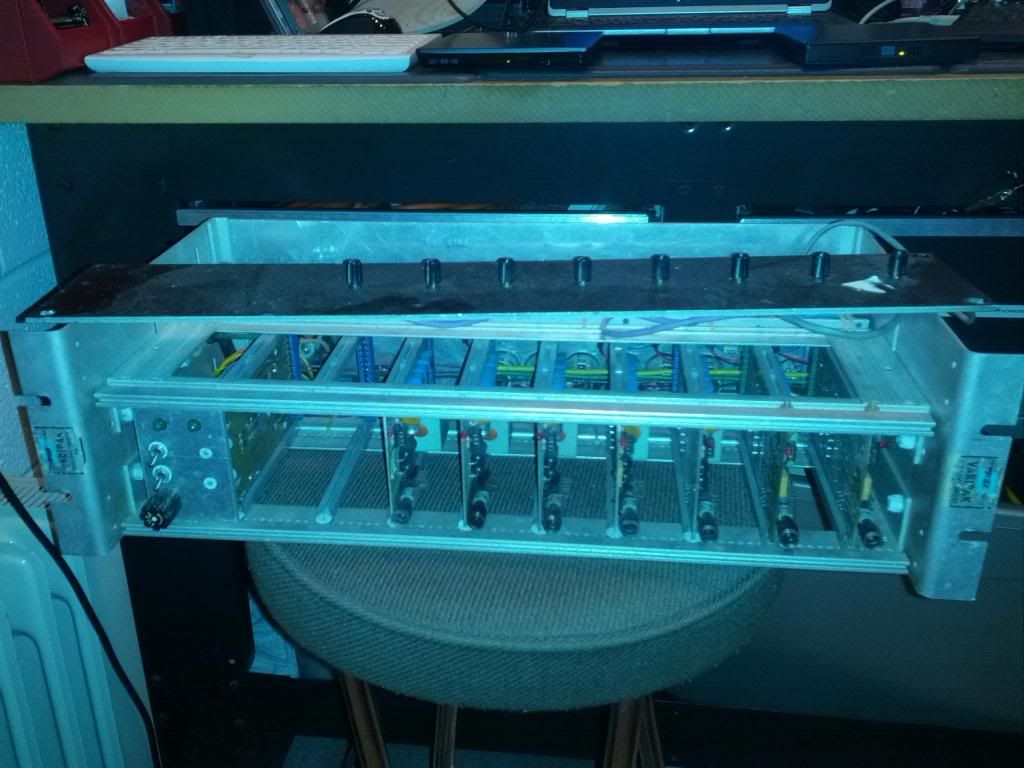
Two years ago - while on vacation with the kids (west coast of Michigan), I found an interesting piece at a roadside antique mall.  It's a 3U Valley People rack with 8 mic pres. 

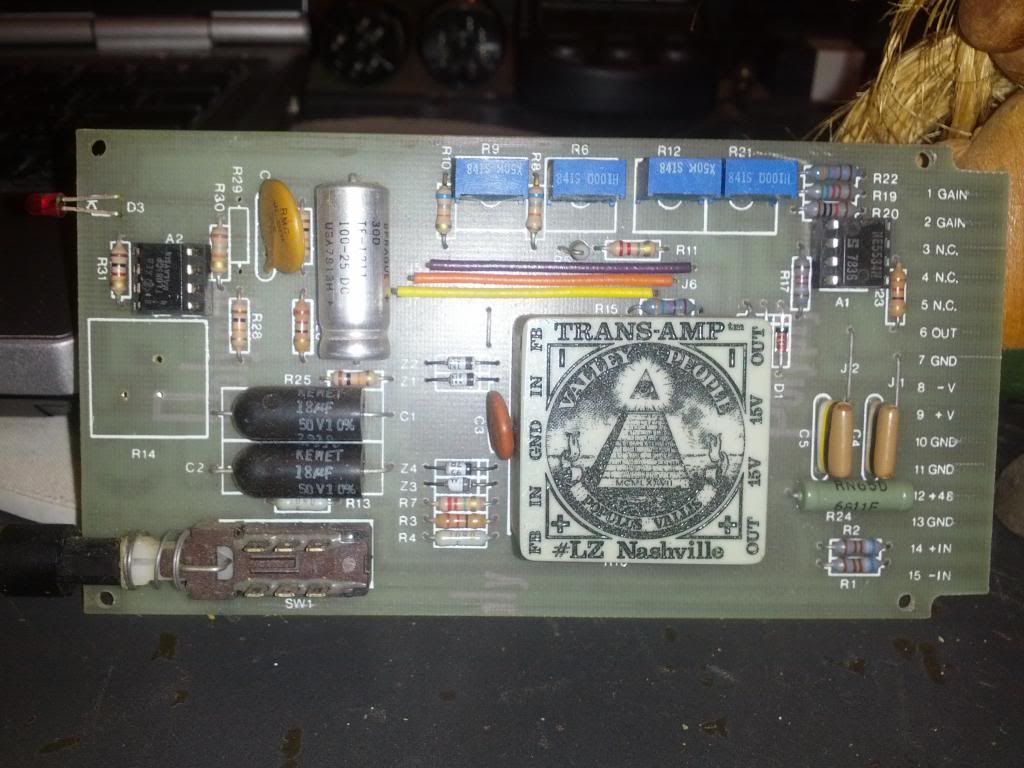
Of all things to find, right?  It looks to be 1970s-era.  The pres say "Valley People Trans-Amp #LZ Nashville".  Each are big, green, square plastic modules - on green PCB cards, with machine traces and hand-soldered resistors, caps, etc.  Cool looking things.

I'd like to recap these and learn their lineage.  Research's uncovered little.  Back of the card says "PC 1000 Rev 0" - though I wonder if these are early MP-1000 pres (Paul Buff).  Says "FB  IN  GND  IN  FB" on the green block (some sort of feedback circuit?). There are a couple chips (op amps?), aside from what's under the big green block (which I assume hides some sort of transistor/chip circuit?).  One chip says, "TLO81CP" (looks to be TI) and the other says, "NE55433N  S 7836".  These easily pop in/out, by hand.

Anyone know anything about these?  I did read in one old post that they were used in MCI's larger boards around '77-78.  Oh, and Frank Zappa used them - supposedly.  And last, not least - does anyone have a schematic?  I found schems linked in old posts, but all have gone dry.

Five of these seemed to work last time I checked; others seemed to need service.  I'm not an electronics expert, but I get by with an iron and a meter.  Any info on getting this back in action much appreciated!

Aj in Michigan
 
Some pics of the cards...

Card


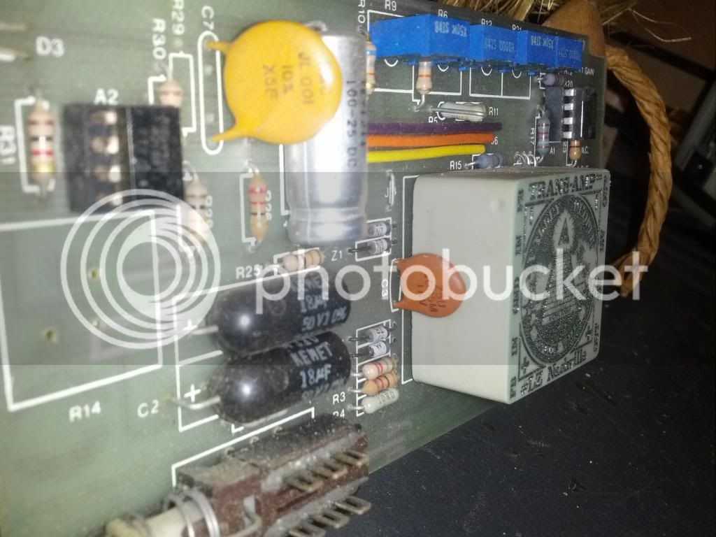
Closer


Green module (angle)


(There's a pair of wide light-brown caps on the other side of the green module, with black/yellow/white banding on each).
 
The green block is the transamp module that Pail Buff sold OEM to other companies with application notes for how to finish them up into working preamps or low noise bus amps. Many people used these back then.

Does the PCB have a company name on it? As you can see Paul was not shy about branding his work.

JR

PS: I described these in general in my old console design article I wrote in 1980...  The app notes are around.
 
Belated thanks for the replies guys... very helpful!
 
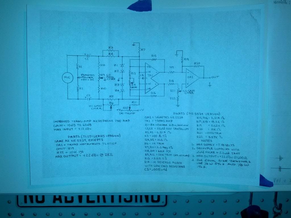
Pucho: I've been digging into your links, and found PDFs that definitely match up with the TransAmp modules these cards have.  Nice reading.  Indeed, the schematic on page 5 of this PDF (and also attached below) seems very close to my card's configuration - but not quite!  For example, the PDF schematic includes an NE55433N op-amp like mine does (right-hand side) but there's no sign of the other op-amp my cards have (the TL081 on the left-hand side)...

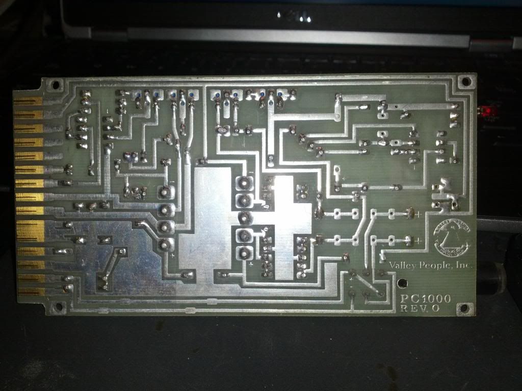
John: I attached a picture of the back of one of these cards.  Definitely looks like an in-house Valley People product (note the logo).  Once again, it says "PC 1000" - which would appear to be the card's exact model #, but the whole Internet seems to know nothing about this particular card.  Weird.

In any case, I mentioned I'm no electronics expert - but I'd like to at least try to get these up and running.  What would you recommend doing to refurb these old cards (even the working ones) to get them ready for daily use?  Test the resistors with a meter, and then start with a re-cap? 

I was thinking about starting with replacing just the two ceramics (C3 & C7).  Some of those other big & funky caps are pretty alien to me - I don't even know where to source them (but I'll try if that's what's needed.)  Also, should I try to replace the op-amps - perhaps with something more modern? Or swap in identical fresh ones?  (Or just leave 'em alone?)

More pics below...

Aj

Back of one of the TransAmp cards:


Closest schematic I could find (it's missing one of the op-amps though):


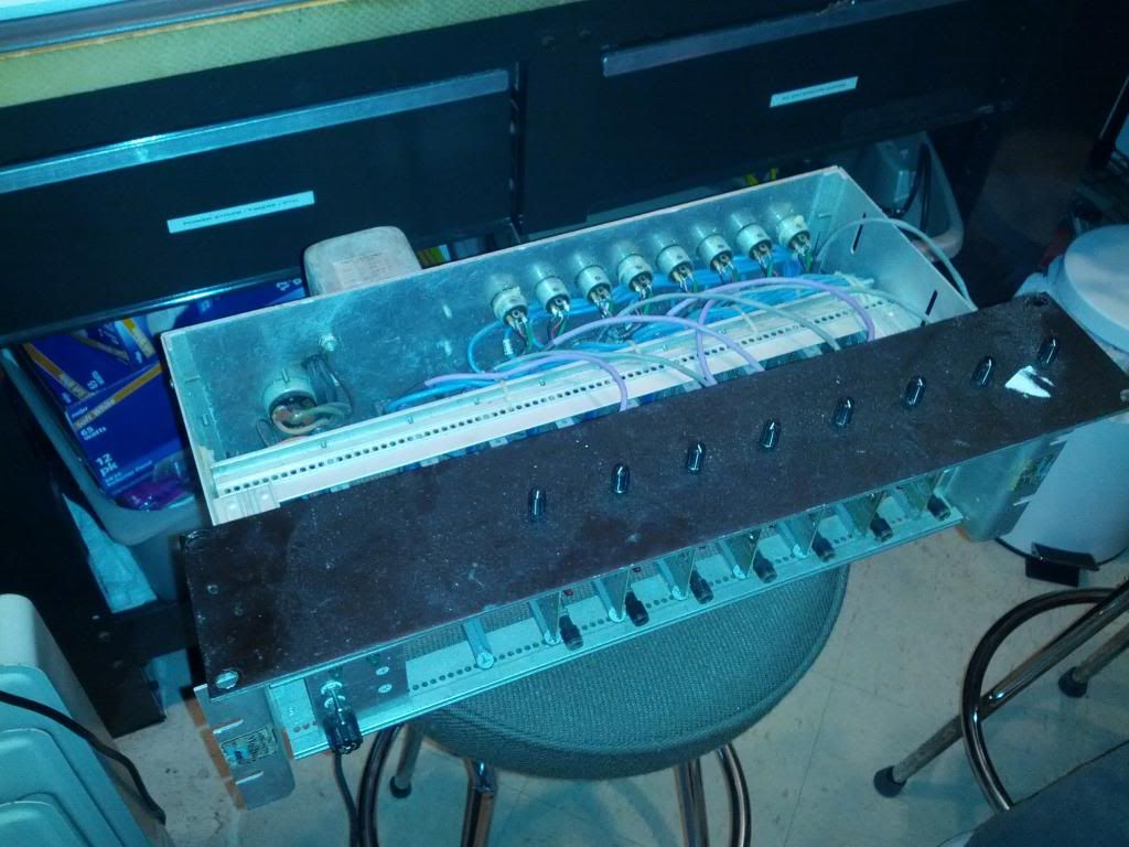
The rack and power supply (with more cards):


Another shot of the rack (note front plate, with gain knobs):


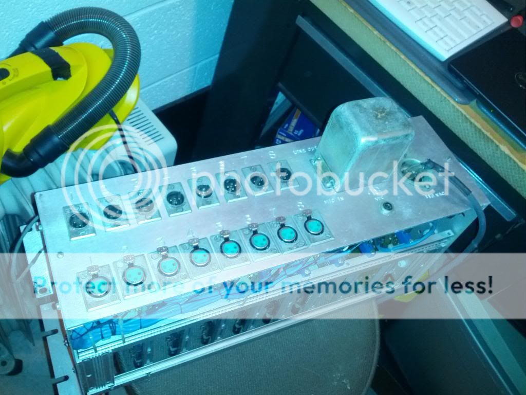
Back of the rack:


The ceramic caps are the LEAST likely component to need replacing.  Start with the two black caps (18uf @ 50v - replace with 22uf @50v) and the large silver one (100uf @ 25v - that value should be available).
 
mjrippe said:
The ceramic caps are the LEAST likely component to need replacing.  Start with the two black caps (18uf @ 50v - replace with 22uf @50v) and the large silver one (100uf @ 25v - that value should be available).
Thanks mjrippe, I'll try those first... any idea why it's best to replace those before all others?  I'm new at working on mic pres - I come from the guitar world, where old ceramics are the devil's spawn. 

Also - any idea where to get those caps?  I can't seem to find any in that odd bullet shape (the 18uf black ones), although I'm not sure it matters.
 
Great Find!

Have you tried powering them on?

I would check the power supply. The electrolytic capacitors (the ones that are larger and polarized) are the ones that will most likely need replacing. Weird values have come and gone. If you can't find a certain value just get the next larger ones, in a design like this, it is NOT as  sensitive as you might think. Especially with power supply. You just run into trouble going too small.

There are some common values that you will easily find at your local electronics store or a place like mouser.com


Have fun
 
abechap024 said:
Great Find!  Have you tried powering them on?

I would check the power supply. The electrolytic capacitors (the ones that are larger and polarized) are the ones that will most likely need replacing.
Yep, it powers up and several of the channels seem to work fine... due to the unit's overall age though, I'm planning on replacing any parts likely to fail (on every card, even the working ones) before putting it back into service.

Electrolytics on the card... how do these parts sound as suitable replacements (from Mouser)?

Sprague TVA1305.5 Aluminum Electrolytic Capacitors - Leaded 50V 20 uF  (replacing C1 and C2 on the TransAmp card)

Sprague TE1211 Aluminum Electrolytic Capacitors - Leaded 100uF 25V +75 -10% (replacing C6 on the TransAmp card)

And finally...!  What about those big, funky looking black/yellow/white caps (at C4 & C5 - see pic below)?  Worth replacing as a first step (and if so, where do I get them - not even sure what they are called)?

Thanks everyone... great thread, big help.

Aj

P.S. Never re-capped a power supply before.  Should I even bother if it seems to be working?  Definitely more comfortable starting with doing the cards, and going from there.  Will do it if needed though.  Basic safety stuff applies, I assume - discharge caps first, etc? 
 

Attachments

  • funky caps.jpg
    funky caps.jpg
    246 KB · Views: 30
OK, it looks like you have a piece of history there. AFAIK Paul did not sell big numbers of stand alone preamps that way, while a number of manufacturers bought the transamp modules to use inside consoles. I bought the modules before rolling my own using some low noise Japanese transistors. 

Since you can't go inside the modules to upgrade caps and opamps inside, I would be inclined to just keep them stock for historical legacy purposes. If some components have failed obviously replace them with good parts but don't expect major sonic changes.

JR


Aj said:
I'd like to recap these and learn their lineage.

Another victim  of the recapping bullshit spreaded by electronic dilettantes on the internet.

In most of the cases the capacitors are not the cause of malfunction.

"Recapping" is ONLY curing problems when:
- there was used a batch of cheap (japanese) electrolytics in the early 70´s - you will recognize them.
- if they are the first series of panasonic SMD-electrolytics from the late 80´s/early 90´s
- when the electrlytic was located near a heatsink or another component which gets hot eg. power resistor
- when the electrolytic was used near its limits (e.g. 48V power rail an a 50V capacitor only)
- when the electrolytic was used in a switch-mode-power-supply (SMPS)

For the rest:
John Roberts said:
If some components have failed obviously replace them with good parts but don't expect major sonic changes.

In specific:
The black 18µF capacitors are tantalum capacitors. Tantalums don´t "dry out", so there is no need to change them unless they show a short with an ohm-meter.

The brown capacitors with color strips are so called "tropical fish" capacitors which are polyester-film capacitors from Phillips (in this case 100nF). No need to replace them except when they are mechanically damaged.

Ceramic Capacitors don´t get broken except mechanically or with exzessive overvoltage.  No need to replace them.  Some ceramics can be microphonic (causing oscillation), but that´s already from the factory.  Can be easily detected by tapping on them with a screwdriver.

The TL081 (together with the LED) is used for a kind of peak-detektor.

 
analogguru said:
Another victim  of the recapping bullsh*t spreaded by electronic dilettantes on the internet.

In most of the cases the capacitors are not the cause of malfunction.

That has not been my hands on experience at all. Nearly every time I've recapped an old piece of audio gear, the sound/noise has substantially improved. I can see certain cases where their might not be much sonic improvement, but almost all cases, especially preamps there is an improvement. It is a fact they electrolytics have a lifespan...its in every part manufactures manual....but to each their own.
 
abechap024 said:
Nearly every time I've recapped an old piece of audio gear, the sound/noise has substantially improved. I can see certain cases where their might not be much sonic improvement, but almost all cases, especially preamps there is an improvement.
That's definitely my experience too... also, parts are cheap, as was this whole unit.  This is essentially a learning project for me, so I'm not too concerned if I overdo some of this (as long as I'm still having fun! :D). 

analogguru said:
The TL081 (together with the LED) is used for a kind of peak-detektor.
Thanks! That makes sense... very cool to have, but it seems the tech who originally racked these hid those handy lights behind the front faceplate!

(Also, just noticed there is a push-button on the left side of each card, also hidden inside the rack! - maybe that's phantom power).

analogguru said:
The brown capacitors with color strips are so called "tropical fish" capacitors which are polyester-film capacitors from Phillips (in this case 100nF). No need to replace them except when they are mechanically damaged.
I knew they looked familiar... they look similar to the caps I've used for guitar tone circuits.  Based on that, I'm going to guess those caps shape the tone (?) of this unit in some fashion.

Anyway, looks like they don't make those anymore - although they are available NOS.  I'm seeing some cracking on the sides of several of them, with the coating coming off (likely heat-related).  Might as well replace those and see if it improves things.
 
abechap024 said:
analogguru said:
Another victim  of the recapping bullsh*t spreaded by electronic dilettantes on the internet.

In most of the cases the capacitors are not the cause of malfunction.

That has not been my hands on experience at all.
Sorry, but your subjective "experience" doesn´t really count. Did you measury any of your "experiences" ?

abechap024 said:
Nearly every time I've recapped an old piece of audio gear, the sound/noise has substantially improved.
Is this improvement only (worthless) subjective corksniffer-impression or did you measure it - if yes, how and what where the results ?  (e.g.: before recapping the measured noise floor was -133 dBm afterwards it was - 143 dBm, measured with Tektronix ........)

abechap024 said:
It is a fact they electrolytics have a lifespan...
Yes, but which lifespan and on what do you base your claimed "fact" ?  On personal measurements or only on hearsay ?
I can tell you that I measured a lot of capacitors from the 60´s and 70´s and they were still fine.  No leakage, no higher ESR and no loss in value, so it is a proven fact that the lifespan of many electrolytics is more than 40 years.....

abechap024 said:
its in every part manufactures manual....
Exactly, they guarantee only 10 years or an amount of hours to avoid that they can be sued.  This doesn´t mean, that electrolytics will be broken after this 10 years.  How many vintage electrolytics did you measure yourself - or is this your only source, the "manufacturers manual" - so only hearsay.

abechap024 said:
but to each their own.
exactly.... as long as technical nonsense from hearsay or cork sniffing isn´t presented as truth or fact.
 
Aj said:
analogguru said:
The brown capacitors with color strips are so called "tropical fish" capacitors which are polyester-film capacitors from Phillips (in this case 100nF). No need to replace them except when they are mechanically damaged.
I knew they looked familiar... they look similar to the caps I've used for guitar tone circuits.  Based on that, I'm going to guess those caps shape the tone (?) of this unit in some fashion.

Anyway, looks like they don't make those anymore - although they are available NOS.  I'm seeing some cracking on the sides of several of them, with the coating coming off (likely heat-related).  Might as well replace those and see if it improves things.
These capacitors are only there for power-supply-decoupling, so a "recapping" won´t change anything in the sound.

All other capacitors don´t need a recapping and WON´T this change anything in the sound. Ceramics and tantalums don´t have a "lifespan" the only electrolytic used is only for the power supply decoupling of the peak-indikator (to avoid click-noise).  A recapping won´t be able to change anything in the sound.... so....

 
@analogguru. I do agree that their is a lot of bogus material floating around on the internet. I for one feel their is a grain of truth to everything.

I deleted the longer response only to say. Yes, yes, yes. Measured, blind test, cork sniffing and not cork sniffing. The best electrolytic is no electrolytic and I've replaced old caps that measured just fine, but the bass sounded very flabby and the IMD we very high. Blind tests and measurements. I don't trust my ears 100% no one should. But I recap all my equipment and am always glad I did and will continue to do so. As I'm sure many many other people will too.
 
I sure don't replace the bolts in my 15 YO car even though they surely have a service life.

If you heard an audible difference after changing a cap that measured good, you didn't measure it properly, and/or you may have inadvertently improved a marginal solder connection or had an expectation bias to hear a difference.

My general advice on the subject, especially with consoles is to first perform baseline measurements for frequency and phase response of "all" the channels compared to each other... If you see a lot of variation channel to channel dig deeper and find out why. If they all are very close, odds are your caps are healthy.

I used to oversize electrolytic caps in series with an audio path, so they could lose a major fraction of their electrolyte, and capacitance before becoming audibly significant.

If you can hear it you should be able to measure it. In my personal experience I can measure things I can't hear, not vice versa, but YMMV.

JR

 
Funny, this morning, going to my job, I´ve seen this post and loved the illuminati-ish logo.

When arrived at the workshop, I had to check some manuals and old papers that were collecting dust in a corner, and know what? I found the same logo in one sheet, I´ve saved the docs, and if you need them I could scan them, just PM, or I could upload them to Technical Documents maybe?
 
JohnRoberts said:
I sure don't replace the bolts in my 15 YO car even though they surely have a service life.

If you heard an audible difference after changing a cap that measured good, you didn't measure it properly, and/or you may have inadvertently improved a marginal solder connection or had an expectation bias to hear a difference.

My general advice on the subject, especially with consoles is to first perform baseline measurements for frequency and phase response of "all" the channels compared to each other... If you see a lot of variation channel to channel dig deeper and find out why. If they all are very close, odds are your caps are healthy.

I used to oversize electrolytic caps in series with an audio path, so they could lose a major fraction of their electrolyte, and capacitance before becoming audibly significant.

If you can hear it you should be able to measure it. In my personal experience I can measure things I can't hear, not vice versa, but YMMV.

JR

I hear what you guys are saying and I know there is truth to it. I guess I would rather just have peace of mind knowing that they are new...
also I should mention my measuring abilities and tools for electrolytic caps is meager at best. I can measure capacitance and DC leakage but don't have the tools nor the time required to REALLY measure each cap to know whether it is still OK for the circuit (ESR, Hysteresis etc etc). Rather pop em out and put the new ones in. Plus a really fun feature of old caps is their capacitance goes way down once they are in the circuit and warm up for a while...aint no one have time for that!

BUT I am interested on learning more about this and will pay more attention next time I recap something and be more scientific I'm sure I have plenty to learn about it... John I always appreciate you chiming in and I know your viewpoint comes with a lot of knowledge and experience...so I guess I need to read some more!
PS fixed way way way more problems with broken gear by replacing the electrolytics then by not...so....I guess that is were my view point is coming from.
 
I wrote about capacitors in my old audio mythology column back on the '80s. You don't need to get out a full test bench to find the most obvious audible deterioration.

Measure the LP pole of the full path... measure the phase response (LF and HF). Perhaps look at square wave response, while I can't guarantee all circuits will not misbehave with wideband square waves. Perhaps band limit the square wave edges rise time first.

Perform some base line tests and know how you gear acts when it is fresh and good.

Human hearing is not very effective for assessing sound quality. What is the reference for comparison? Live sound?

The ear has poor short term memory, and can hear subtle differences but the hard part is knowing which one is correct, if either one is. Often just standing in a slightly different spot in the room will change the sound received.

Often the not very exotic measurements like frequency response, S/N ratio, and distortion will dominate how a signal path will sound.

JR


Latest posts

Back
Top