Balanced output transformer for Roland RE - 201

GroupDIY Audio Forum

Help Support GroupDIY Audio Forum:

This site may earn a commission from merchant affiliate links, including eBay, Amazon, and others.

smilan

Well-known member
Joined
May 29, 2017
Messages
469
I would like to add a balanced output to my Roland RE-201 echo machine.
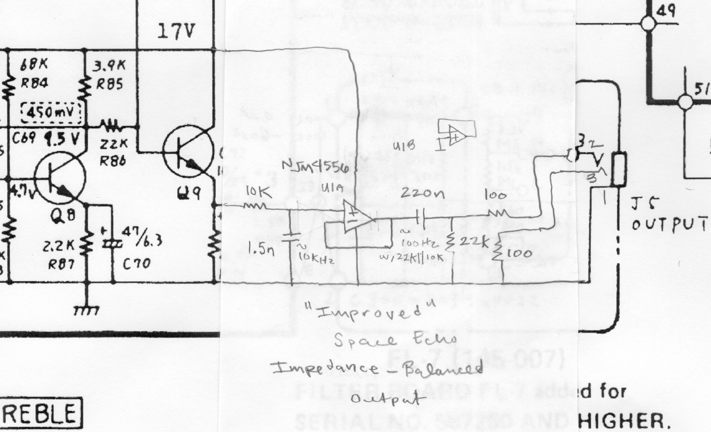
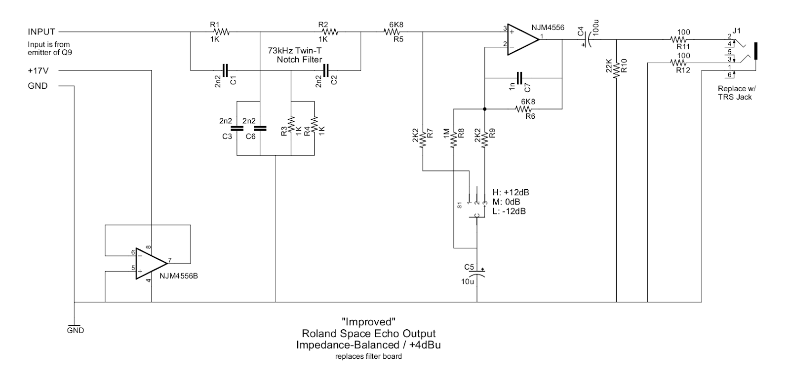
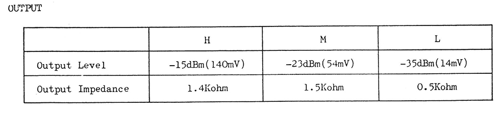
The output impedance  and levels are as follows:
output.jpg

I'm looking at the Jensen line output transformers
https://www.jensen-transformers.com/transformers/line-output/
and don't sure which one to choose.
Any suggestions?
 
I see that the output impedances are relatively high.
Most (output)  transformers like to be driven from a low impedance.
(Driving from a high impedance will increase distortion and may affect the frequency response.)
 
As I expected, the output selects a tap on a voltage divider.
When you look at the schematic, it may be a better option to connect an output transformer directly through a capacitor to the emitter of the transistor (Q9) in the output stage.
(Or eventually lower the value of R89, or omit it completely.)
 

Attachments

  • 201.png
    201.png
    88.7 KB · Views: 31
The output of space echo is so bad it really deserves to be upgraded. I don't think that "filter board" even does anything. At least I can't figure it out.

Here is an impedance-balanced output that would be a lot better in a number of ways:

[removed - see new circuit below]
 
RuudNL said:
I would increase the value of the 0.22 output capacitor.
Yeah, you're probably right about that actually. Could be a source of LF noise and plugging into some old 600 ohm gear will loose LF. Might as well just make it big like 100u.

But there should be a high-pass somewhere. That's just another reason to make a proper PCB so that the circuit can be a little more elaborate.
 
squarewave said:
Here is an impedance-balanced output that would be very simple to implement on a piece of perfboard:

SpaceEchoZbalOut.png
Thanks a lot! I like this solution, right now I don't have a 4556, can I use NE5534  instead?
 
I've been down this road.  I don't think you want unity gain anyway, some gain is probably useful. 
 
squarewave said:
Updated my original post with a much better circuit that incorporates the switch and adds gain.
Thanks a lot squarewave, tomorrow I'll try to get  a 4556 around here and build it.
 
smilan said:
Thanks a lot squarewave, tomorrow I'll try to get  a 4556 around here and build it.
It doesn't have to be a 4556. That part is ideal because it has a low quiescent current, it's low noise and has a lot of power (+-70mA output). You can use any op amp as long as it's not high-speed (because they require proper bypassing which is not present) and it's stable at the gain used. So a 5532 would be fine. A 5534 would also be fine if you use the second circuit I posted because it has gain and a feedback cap that will stabilize it. A TL0X would also be fine but it won't have as much drive capability.
 
Here are some pics of the filter board in my RE-101 (Japanese version w/ tweaked primary wires for 117AC):

SpaceEchoOut2.png


SpaceEchoOut1.png


So the wiring is a little delicate. This is not an easily reversible operation so care should be exercised. Note that even though the switch is 3 poles, it's just being used as one.

I will probably try to make a little board for this. But the first step is to find a TRS jack that is that style and design the board around that since that is clearly the mounting point for it.

UPDATE: Ok, I just realized that filter is a twin-t notch filter at 72kHz. So that's a little bit of a problem. Will need to think...
 
Ok, here's a completely re-designed circuit:

SpaceEchoZbalOutN.png


UPDATE: There is a mistake in this circuit. The disabled op amp + input should be connected to the + terminal of C5 (or the input) and not GND.

This just combines the twin-t notch filter and of course it has the impedance balacenced out. The LMH switch is used to provide attenuation / gain of -12dB, 0dB and +12dB respectively. So M position is vaguely what the H position was and then H becomes +12dB. That should be enough of a boost. I don't want to push it. Resistors could be tweaked if desired.

If anyone sees a problem with this please let me know. I'll probably draw up a little board for this, submit it to OSHPark and try it in my RE-101. It will just be soldered directly to this jack (Amphenol Audio ACJS-MN3):

acjm_mn_2_SPL.jpg


So it should just be a bolt-on and then 3 wires in and 3 wires to the switch.
 
I can't find an NJM4556A  here in TLV, the man from the electronics shop told me that I can use AD712 as a replacement , does the AD712 will work in this application?
I can also get a NJM4558.
 
No, AD712 is a fancy high-speed amp. NJM4558 is fine. Your NE5534 is better. But look at the datasheet because below a gain of 3 it needs an extra little "compensation" capacitor between pins 1 and 8. You probably want a little gain anyway. If you use a fixed network of 6.8K and 2.2K and 100u cap like in my last circuit, that's 12dB aka a gain of 4.

However, unlike my first schematic, I have since determined that you need that filter network. It filters out high frequency tape bias signal. But realize that the existing jack is not TRS and it's mounted to the existing filter network board. So it's not particularly easy to reuse that. Be careful not to irreversibly hack-up your machine. There are larger problems to overcome than determining which op amp to use.
 
Thanks, I have this veroboard and this TRS jack so I think I can build your latest circuit on this veroboard and replace the original one with this one.
This is what I've done so far.
I'll add the other components later
96818724-272150827487587-44847.jpg


I looked on the datasheets of the 4556 and the 4558 but couldn't find the  "Output Current ( IO=70mA on the 4556 ) " on the 4558 datasheet.
As far as "Large Signal Voltage Gain " both op amps having the same values, between  86-100 dB.
 
Ok. That board looks a little large for the space but if it fits, that should work. Here's a layout of my latest circuit it helps:

SpaceEchoZbalOutLayout.png


Note that the op amp is biased from the DC at the emitter of the "Q9" transistor. So the other challenge will be that you'll need to unscrew the main PCB and lift it away enough to tack some wires on the bottom. Generally, you want the power and ground wires to run next to each other to minimize EMI. So you will want to take +17V from the collector of Q9, signal from the emitter and then ground from whatever the nearest ground is (the ground side of the emitter resistor probably). That's the 3 wires you need to power the board and provide signal. Then you just have the 3 wires to the switch (if you're using that). If you are using the switch, be careful not to overheat the leads. That switch looks a little delicate. You could melt stuff inside and break it and it could be very difficult to replace.

Again, I wouldn't worry about op amps too much. JRC4556 and JRC4558 are actually not related at all. JRC4558 is actually a very mediocre amp whereas JRC4556 is actually quite good. But just about any amp works in this scenario provided that it doesn't require bypass caps at the power pins (which you don't have and cannot add because the amp is running single supply) so just don't use a fancy new high speed amp. Use whatever has the best drive capability.
 
For posterity here are some measurements from my RE-101:

Oscillator board claims 60kHz but filter board is tuned to 72kHz. Measured my oscillator at 61.7kHz. So it's missing the notch by quite a bit.

H output is supposed to make 390mVpp with spec'd input levels. With 138mV on Instrument input, I measured 300mVpp on H output. Mic with 2.4Vpp measured only 109mVpp on H output. So mic outputs are really low for some reason.

Monitoring echo with +3dB VU input, I measured ~1.6Vpp on H output. If I blast the input, the output maxes out at ~2Vpp. And I know it's not just upstream clipping because it has characteristic tape saturation and frequency loss. Although my tape is very very old.

With planned op amp output supply of 17V, it can probably only swing ~14Vpp.So a boost of 12dB is probably about the limit. Another 4-6dB would clip the output.
 
Back
Top