You are using an out of date browser. It may not display this or other websites correctly.
You should upgrade or use an alternative browser.
You should upgrade or use an alternative browser.
[BUILD] 1176 Rev A - Back to the beginning...
- Thread starter mnats
- Start date


Help Support GroupDIY Audio Forum:
This site may earn a commission from merchant affiliate
links, including eBay, Amazon, and others.
Jase_Sanderson
Active member
- Joined
- Jan 10, 2014
- Messages
- 35
mnats said:Jase666 said:Hi,
I know it must be in here somewhere cause i'm seeing a few posts with problems with r33, sorry for being a newb but can't find what i'm looking for.
Having built my Mnats/Hairball 1176 revA, my heads spinning out that there's smoke coming from r33 (panic). I built it slowly and took extra care following all the instructions from the Hairball and Mnats site.
I checked each component with a DM before soldering and although its not the neatest cable job (need to tidy them up) they all seem fine.
I've been googling all day and I've started reading all this amazing long thread but there's a lot to take in, it's my first DIY build and I'm thinking i should have tackled something easier.
First off is this a common situation, if so i couldn't see it in the FAQ?
In a google search i saw someone saying they had a similar thing and it was q6 to blame but when i looked for the rest of the guys post i couldn't find it.
Any pointers
Since that resistor is in series with a capacitor, there isn't any way for DC to pass through and cause this resistor to smoke. It's equally unlikely that there is enough AC signal to cause damage.
Check for shorts and confirm you are referring to the correct resistor. Most seem to have problems with R32, normally caused by ignoring the output transformer legends printed right on the PCB.
Sorry I meant r32..ooops! Can't find any shorts, will double check the legends to the output transformer but i'm sure they are fine
Question. I am really happy with my REV A, but i would prefer a little more range with the attach and release times. I read in the forum that you can use higher rated pots to extend the range. Is that correct?
I and thinking that the way it is currently behaving is indicative of the original REV A, i would just like it to have slightly slower release and attack time available. I still want it to be fast when needed.
I know its designed to be a fast limiter, but i feel i get much more range out of the UA REV D's and Urie's
Cheers.
Every BOM for the REV A, REV D, G1176 use 25k for attack, and 5M for release... something must be wrong with my unit?
It just doesn't grab the transient the same as im used too. and you cant hear the release as much as other units..
maybe my transistors in the gain reduction circuit are not right..
It just doesn't grab the transient the same as im used too. and you cant hear the release as much as other units..
maybe my transistors in the gain reduction circuit are not right..
Echo North
Well-known member
musicalsl said:Every BOM for the REV A, REV D, G1176 use 25k for attack, and 5M for release... something must be wrong with my unit?
It just doesn't grab the transient the same as im used too. and you cant hear the release as much as other units..
maybe my transistors in the gain reduction circuit are not right..
Check the R and C values in parallel with those pots.
Echo North
Well-known member
Jase666 said:mnats said:Jase666 said:Hi,
I know it must be in here somewhere cause i'm seeing a few posts with problems with r33, sorry for being a newb but can't find what i'm looking for.
Having built my Mnats/Hairball 1176 revA, my heads spinning out that there's smoke coming from r33 (panic). I built it slowly and took extra care following all the instructions from the Hairball and Mnats site.
I checked each component with a DM before soldering and although its not the neatest cable job (need to tidy them up) they all seem fine.
I've been googling all day and I've started reading all this amazing long thread but there's a lot to take in, it's my first DIY build and I'm thinking i should have tackled something easier.
First off is this a common situation, if so i couldn't see it in the FAQ?
In a google search i saw someone saying they had a similar thing and it was q6 to blame but when i looked for the rest of the guys post i couldn't find it.
Any pointers
Since that resistor is in series with a capacitor, there isn't any way for DC to pass through and cause this resistor to smoke. It's equally unlikely that there is enough AC signal to cause damage.
Check for shorts and confirm you are referring to the correct resistor. Most seem to have problems with R32, normally caused by ignoring the output transformer legends printed right on the PCB.
Sorry I meant r32..ooops! Can't find any shorts, will double check the legends to the output transformer but i'm sure they are fine
If you are absolutely sure your OT is wired correctly you may have a damaged Q6.
Echo North
Well-known member
jimkeaney said:musicalsl said:So my unit work and sound fine. But am unable to complete step 3 in the calibration process.
The VU meter responds the
Way I'd expect in +4 and GR. the different ratios appear to work the way they are intended. Not sure why I can't do the last step though..
Funny, I noticed this last night when calibrating too. Looks like the calibration instructions left out the part where you turn R44 trimmer to get -10, then re-zero. Looks like it just got updated recently. http://www.hairballaudio.com/blog/d_assembly/reva/calibration/
Should be corrected now.
preampniak
Member
- Joined
- Feb 12, 2014
- Messages
- 5
Is it ok to use a 10k resistor on R11? The board says 10k but the hairball BOM says to use a 9.1k resistor. Are all of the values correct that are on the v1.2.5 05.12.10 board?
hymentoptera
Well-known member
preampniak said:Is it ok to use a 10k resistor on R11? The board says 10k but the hairball BOM says to use a 9.1k resistor. Are all of the values correct that are on the v1.2.5 05.12.10 board?
This was also asked in post #1084 of this thread, but I don't think it was ever really answered as to why the change to 10k, then back again. The schematic certainly shows 9k1, and that's what every one's using. R11 forms part of a voltage divider with R12 (2k2) for what appears to be the feedback loop in the input Signal PreAmp section, and is also part of Q2'd drain resistor, again together with R12 in series to ground, so I should assume that altering R11's value would have an effect on the overall gain on the input Signal PreAmp section.
R11 also has a 6.8uF cap in parallel, but I'm not sure as to it's purpose. Note that Q4 (the other J309, in the output Line Amp ) has a similar configuration, although with a much high ratio between the two resistors R27 (12k) and R28 (560R), presumably to affect the different current and gain needs of driving a transformer?
According to post #49 in the linked thread below, the famous "Plosives thread", Ed Anderton, who I think reverse engineered the input and output transformers and makes the very ones found in this kit, apparently made the suggestion to change R11 to 9k1.
http://groupdiy.com/index.php?topic=34502.40
EdAnderton himself mentions earlier in post #4 of the "Plosives" thread however that (If I'm reading this right) that the change is actually a change found on the schematic moving from the original 1176 (appx first 124 units) to the Revision A. If that's teh case, then 9k1 would be the correct value according to all schematics for the Rev A, and therefor the one we should be using.
I would recommend sticking with 9k1 here, it's not an uncommon resistor value really, belonging to the E24 series and probably manufactured by all the major brands. But to answer your question, in my opinion, yes, I think 10k would work here as well. But I would love to know the difference. For instance, is it just a gain thing?
I'd love to hear more from an expert on this circuit as to the actual function of R11 and surrounding components.
Anyone?
Greetings all. I was trying to start the calibrations but I'm having an issue with my VU meter. It's being intermittent and overall strange. Nothing happening at all in GR mode. But I've ran drums through the unit and the compression sounds exactly like I would expect. The line amp sounds great. All audio seems to be right on. But the VU meter is totally on the fritz. I've got to wiggle the actual VU box around for the needle to be responsive in +4 mode. And the input and output have to be cranked and then it jumps up to +2 and dances around there between 2 and 3. It never goes below that. So it can only move up and down when it's past +2. Then it stops working abruptly and pins itself there. I have to tap on it to get it to come back down. I've checked my voltages with the schematic and all is looking well except for Q4 which is showing 4.37. R24 and R25 are the correct values. I've checked and even rewired the meter PCB and meter itself.
I do realize the possibility that this meter is just a lemon.
Please advise.
Thanks.
I do realize the possibility that this meter is just a lemon.
Please advise.
Thanks.
dbonin
Well-known member
It is possible it's a lemon, but I've yet to see a bad meter.
Make sure you have not over tightened the screws that hold the meter to the face plate.
Make sure you have not over tightened the screws that hold the meter to the face plate.
MountCyanide said:Greetings all. I was trying to start the calibrations but I'm having an issue with my VU meter. It's being intermittent and overall strange. Nothing happening at all in GR mode. But I've ran drums through the unit and the compression sounds exactly like I would expect. The line amp sounds great. All audio seems to be right on. But the VU meter is totally on the fritz. I've got to wiggle the actual VU box around for the needle to be responsive in +4 mode. And the input and output have to be cranked and then it jumps up to +2 and dances around there between 2 and 3. It never goes below that. So it can only move up and down when it's past +2. Then it stops working abruptly and pins itself there. I have to tap on it to get it to come back down. I've checked my voltages with the schematic and all is looking well except for Q4 which is showing 4.37. R24 and R25 are the correct values. I've checked and even rewired the meter PCB and meter itself.
I do realize the possibility that this meter is just a lemon.
Please advise.
Thanks.
Yep, they're not overtightened. It's not even screwed in at the moment. That's how I'm able to wiggle it. I was thinking I had something on the meter pcb wired wrong so I redid it. No change.
I've seen at least 2 lemons in this thread. And the one on page 97 isn't too far from my symptoms.
I've seen at least 2 lemons in this thread. And the one on page 97 isn't too far from my symptoms.
Echo North
Well-known member
MountCyanide said:Yep, they're not overtightened. It's not even screwed in at the moment. That's how I'm able to wiggle it. I was thinking I had something on the meter pcb wired wrong so I redid it. No change.
I've seen at least 2 lemons in this thread. And the one on page 97 isn't too far from my symptoms.
If it's not working in +4 and just acting intermittently that is probably a bad meter. I think I have an email from you, I'll get a replacement out.
Mike
Thanks, Mike.
keevhren
Member
Hey Mike!
Just a quick question... I finished assembling my first 1176 yesterday and realized that I still had the lone ground wire coming off of the output transformer. I looked through the build guides and didn't see anything about it but after some googling, I found this picture on a gear slutz thread:
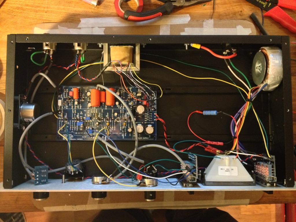
It appears that this person has sent the ground wire to PCB but I can't tell where it's connected and my other searches came up moot. Any help would be much appreciated! Once I've got this in place it's time to calibrate!
Just a quick question... I finished assembling my first 1176 yesterday and realized that I still had the lone ground wire coming off of the output transformer. I looked through the build guides and didn't see anything about it but after some googling, I found this picture on a gear slutz thread:
It appears that this person has sent the ground wire to PCB but I can't tell where it's connected and my other searches came up moot. Any help would be much appreciated! Once I've got this in place it's time to calibrate!
Echo North
Well-known member
The frame of the output is grounded to the enclosure by the screws. Just cut that bare wire.
hymentoptera
Well-known member
keevhren said:Hey Mike!
Just a quick question... I finished assembling my first 1176 yesterday and realized that I still had the lone ground wire coming off of the output transformer. I looked through the build guides and didn't see anything about it but after some googling, I found this picture on a gear slutz thread:
[]
It appears that this person has sent the ground wire to PCB but I can't tell where it's connected and my other searches came up moot. Any help would be much appreciated! Once I've got this in place it's time to calibrate!
Looks like they tied the circuit ground in there. I guess this would work, as long as the transformer is properly grounded to chassis another way.
I would recommend making a second ground point (NOT the same point where safety earth connects to chassis) for your "star ground" and tying any grounds there. Drill a hole (or use one of the extra existing holes) somewhere near the XLRs and output transformer, run a small bolt and nut, with a star washer, and connect the transformer's drainwire there, and also connect circuit ground there too. Typically we grab circuit ground at the negative side of one of the big 2200uF PSU filter caps.
edit: nm, Mike posted while I was typing. If he says to snip it, then snip it
")
Jase_Sanderson
Active member
- Joined
- Jan 10, 2014
- Messages
- 35
Hairball Audio said:Jase666 said:mnats said:Jase666 said:Hi,
I know it must be in here somewhere cause i'm seeing a few posts with problems with r33, sorry for being a newb but can't find what i'm looking for.
Having built my Mnats/Hairball 1176 revA, my heads spinning out that there's smoke coming from r33 (panic). I built it slowly and took extra care following all the instructions from the Hairball and Mnats site.
I checked each component with a DM before soldering and although its not the neatest cable job (need to tidy them up) they all seem fine.
I've been googling all day and I've started reading all this amazing long thread but there's a lot to take in, it's my first DIY build and I'm thinking i should have tackled something easier.
First off is this a common situation, if so i couldn't see it in the FAQ?
In a google search i saw someone saying they had a similar thing and it was q6 to blame but when i looked for the rest of the guys post i couldn't find it.
Any pointers
Since that resistor is in series with a capacitor, there isn't any way for DC to pass through and cause this resistor to smoke. It's equally unlikely that there is enough AC signal to cause damage.
Check for shorts and confirm you are referring to the correct resistor. Most seem to have problems with R32, normally caused by ignoring the output transformer legends printed right on the PCB.
Sorry I meant r32..ooops! Can't find any shorts, will double check the legends to the output transformer but i'm sure they are fine
If you are absolutely sure your OT is wired correctly you may have a damaged Q6.
Yes you're right, I changed the Q6 and no smoke. fixed, Ace! Thanks so much! Will give it proper test after calibration tomorrow, wish me luck!
Glorious. The new VU is bouncing.
Now on with calibration.
Thanks for the great customer service Mike.
Now on with calibration.
Thanks for the great customer service Mike.
From Glorious to..... :-[
I made it through the first 2 calibration steps. But the third one, yikes. It turned into a bit of a mess. I couldn't get the R44 trimmer to decrease the meter. I couldn't get it to do anything. It seemed dead. So, having bought a spare, I swapped it out. Nothing. I stuck my DMM on the original 5k and it read 3.6 or so, twisted the knob and it actually seemed to be working. Desolder again. (Yeah I know but that's anll hindsight, regrets, etc) And now I see that the uppermost lead pad and the wiper pad seem to have the trace covering scraped off. Is that an issue or non-issue, they are connected in the circuit, right? Also, yes there's more, the lowermost lead pad is partially lifting. Yes, here's where the yikes comes into play. What I'm thinking is, (with my excessive or misguided proactiveness) with these pads in a bit of a mutilated state, there's an alternate trimmer with its own pads to the left of this. Can I find that one at mouser or somewhere and pop it in there? I'm here asking for guidance because I know that my poking around is good for my bravado and desire to learn but at a possibly severe detriment to the success of this build.
So, war and peace later, is this a good idea and what is that alternate trimmer?
:-[I made it through the first 2 calibration steps. But the third one, yikes. It turned into a bit of a mess. I couldn't get the R44 trimmer to decrease the meter. I couldn't get it to do anything. It seemed dead. So, having bought a spare, I swapped it out. Nothing. I stuck my DMM on the original 5k and it read 3.6 or so, twisted the knob and it actually seemed to be working. Desolder again. (Yeah I know but that's anll hindsight, regrets, etc) And now I see that the uppermost lead pad and the wiper pad seem to have the trace covering scraped off. Is that an issue or non-issue, they are connected in the circuit, right? Also, yes there's more, the lowermost lead pad is partially lifting. Yes, here's where the yikes comes into play. What I'm thinking is, (with my excessive or misguided proactiveness) with these pads in a bit of a mutilated state, there's an alternate trimmer with its own pads to the left of this. Can I find that one at mouser or somewhere and pop it in there? I'm here asking for guidance because I know that my poking around is good for my bravado and desire to learn but at a possibly severe detriment to the success of this build.
So, war and peace later, is this a good idea and what is that alternate trimmer?
Similar threads
- Replies
- 10
- Views
- 1K