[BUILD] 1176 Rev A - Back to the beginning...

GroupDIY Audio Forum

Help Support GroupDIY Audio Forum:

This site may earn a commission from merchant affiliate links, including eBay, Amazon, and others.
Chrome Heart said:
So how different sonically, is the Hairball Rev D from the Rev A? Has anyone build both?  It looks like they use the same Tx's in the kit.

Different gain stages. The REV A is FET based the D is BJT based. The GR reduction FET also is missing a source resistor in the A.  What does all this add up to? The Rev A is a little more quick to distort and crunchier.  Typically people love it on snare, electric guitar, or an aggressive vocal.

Mike
 
Hairball Audio said:
Chrome Heart said:
So how different sonically, is the Hairball Rev D from the Rev A? Has anyone build both?  It looks like they use the same Tx's in the kit.

Different gain stages. The REV A is FET based the D is BJT based. The GR reduction FET also is missing a source resistor in the A.  What does all this add up to? The Rev A is a little more quick to distort and crunchier.  Typically people love it on snare, electric guitar, or an aggressive vocal.

Mike
Thanks Mike.  I appreciate the details. 
 
Chrome Heart said:
Hairball Audio said:
Chrome Heart said:
So how different sonically, is the Hairball Rev D from the Rev A? Has anyone build both?  It looks like they use the same Tx's in the kit.

Different gain stages. The REV A is FET based the D is BJT based. The GR reduction FET also is missing a source resistor in the A.  What does all this add up to? The Rev A is a little more quick to distort and crunchier.  Typically people love it on snare, electric guitar, or an aggressive vocal.

Mike
Thanks Mike.  I appreciate the details. 
Are you still expecting to have complete Rev D kits first week of March?
 
Chrome Heart said:
Chrome Heart said:
Hairball Audio said:
Chrome Heart said:
So how different sonically, is the Hairball Rev D from the Rev A? Has anyone build both?  It looks like they use the same Tx's in the kit.

Different gain stages. The REV A is FET based the D is BJT based. The GR reduction FET also is missing a source resistor in the A.  What does all this add up to? The Rev A is a little more quick to distort and crunchier.  Typically people love it on snare, electric guitar, or an aggressive vocal.

Mike
Thanks Mike.  I appreciate the details. 
Are you still expecting to have complete Rev D kits first week of March?

Yup, we're just waiting on output transformers.
 
Hi,

Powered up and no smoke!!!
getting 28.66v and -10.26v, have changed out the input txf as the one ive wound for some reason somethings wrong?
getting signal to output but without sine wave in when i turn the q bias CCW i get a sine wave!!!? oscillation, looks suspiciously like 1K?
might need to redo output txf as well as wave form is pretty messed up!! will do some photos tomorrow, shattered and eyes are going now!

Spence.
 
How off will everything be if I am at 28.66v and -10.26?
- rail is within 0.5v but I've used a 1.2k rather than 1.1k, should, I change or is 28.66v going to be ok?

Spence.

on second test i was getting 28.99v
 
found a problem in my wiring and changing transformers has made a massive difference, very strange, ive wired the output transformer to how it should be but wave form is very distorted?
will investigate further once i get some peace time!!

Spence.
 
Noticed I had wired up the feedback loop and the other secondary wrong I think, so changed round?
Now getting R32 smoking and glowing red!!!!!
The txf making some very strange sounds, I have obviously not got the winds right on the output txf, but I had been advised by CJ about a 22 to 1 relationship of the winds on 1 for the feedback winding,  so I ended up with only a few winds for the feedback loop.
Does anyone have any other information for winding either txf for the 1176 blue stripe?
I'm kinda stumped without winding the output txf correctly.

Regards

Spence.
 
Found my calculations!!!
On one winding I have 630 turns, then 630 turns on another, then 2 X 150 turns wired in series to give 300 turns then 12 turns for feedback. This is with 0.315mm wire allowed a bit of space for insulation and lams just get on there on the EI45.
Could anyone explain why R32 with 12 winds of 0.315mm is blowing up?

Regards

Spence.
 
Also I've just had a look at the windings that the EA-5002 has

http://library.hairballaudio.com/datasheets/5002.pdf

On the secondary it has two 150ohm windings which are put in series, and it then says 600ohm?
Shouldn't this be 300ohm or am I missing something?
I am doubting everything and confused again!!!

 
Have looked at calculations again and might be a bit off.
I can get a max turns on bobbin of 1700 with 0.315mm.
PRI of 600ohm = 540 turns, Feedback loop = 24,  I've devided PRI by 22.
SEC 2 winds would then be 270 turns each to give 540 when in series.
The last SEC would be 540 turns, giving me a total turns of 1644 leaving me space for insulation between winds.
Also I need to isolate the middle lam for DC gapped.
Can anyone see any problems with this?

Spence.
 
So many questions about these transformers!!!
Does the 150ohms on each of the secondaries of the output txf mean that when in series yes it would be 300 ohm but then in relationship which the primary it would then see 600 ohm on secondary and 1200ohm on primary and 1200ohm on other secondary?

The input txf is now confusing me as sowter does one that is 1:1.58, cinemag does one that is either 1:5 or 1:10, these are both quite far apart ratio wise? Could anyone explain what is the reason for this please?

Regards

Spence.
 
Spencerleehorton said:
So many questions about these transformers!!!
Does the 150ohms on each of the secondaries of the output txf mean that when in series yes it would be 300 ohm but then in relationship which the primary it would then see 600 ohm on secondary and 1200ohm on primary and 1200ohm on other secondary?

The input txf is now confusing me as sowter does one that is 1:1.58, cinemag does one that is either 1:5 or 1:10, these are both quite far apart ratio wise? Could anyone explain what is the reason for this please?

Regards

Spence.

Are measuring the DC resistance?  That's VERY different than the AC impedance of a transformer. What's listed in ohms on the data-sheet is AC impedance. DC resistance will always be very small.
 
well ive been having a bit more of a play and it seem my output txf does work ok now, had a winding the wrong way round which was giving me oscillation!, still not out of the woods as the waveform is seriously messed up on output.
+4 meter mode im not getting anything from meter, +8 is acting like GR and GR seem fine but does quite get to 0 when adjusting.

Spence.
 
Spencerleehorton said:
well ive been having a bit more of a play and it seem my output txf does work ok now, had a winding the wrong way round which was giving me oscillation!, still not out of the woods as the waveform is seriously messed up on output.
+4 meter mode im not getting anything from meter, +8 is acting like GR and GR seem fine but does quite get to 0 when adjusting.

Spence.

Check your DC bias voltages against the schematic with voltages on the MNATS.NET site.
 
hello

im building the Hairball 1176 rev.A / Rotary version. unit powers up, it works well as an amplifier, but..
.. it does no GR. Q Bias doesnt change output level at all - tho it does change DC, based on quick measurements.

so far what i measured:
* PSU seems to be ok, +29.8V-ish and -9.7V-ish (2 diff. DMMs show slightly diff. results)
* i use 2N5088 in places of of 2N3707s (all way above 400 hFE)
* DC voltages are in the ballpark - very close to whats labeled in the "1176REVA_125_VOLTAGES.pdf"
* attack and release seem to work,  they change the DC - checking it on scope, with drum recording input.
* at point 19 i seem to have similar to this on scope : http://www.axtsystems.com/joomla31/images/articles/1176LN/d3_d4_cathode.gif
* i got the signal on point 7
* the GR/VU switch board does short point 22 to GND at "OFF" position
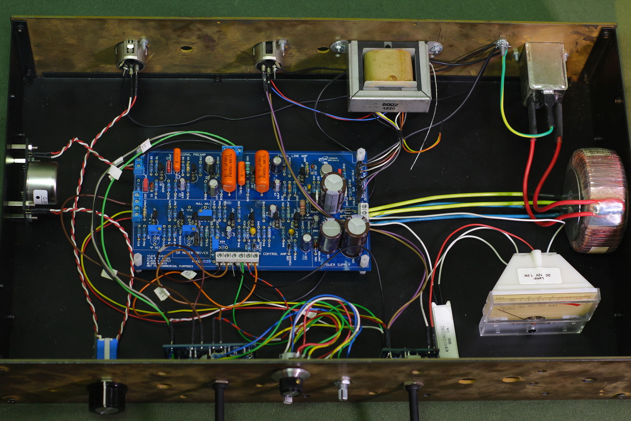
IMG_7162_revA.jpg


a clooser look:

IMG_7163_revA_closer_Z.jpg


a quick look at the bottom / soldering :

IMG_7164_revA_bottom_Z.jpg

obviously this is not the final wiring, i just wanna to see how much the shielded cables actually help with the noise.

do you have ideas?
will post more measurements, photos - whatever needed to figure out / fix my problem.

thank you.
 

Latest posts

Back
Top