letterbeacon
Well-known member
Inspired by DaveP's great thread, I decided to build myself an RCA BA-6A limiter. After being lucky enough to buy the original input and output transformers from emmr, I became a bit obsessed with building it as close to the original as possible. This means using NOS RCA tubes throughout, carbon comp resistors pretty much throughout, and paper in oil capacitors where specified in the BOM. I know I know, this isn't the most efficient way to build this limiter -there are plenty other cheaper, less noisier ways to do it, but indulge me!
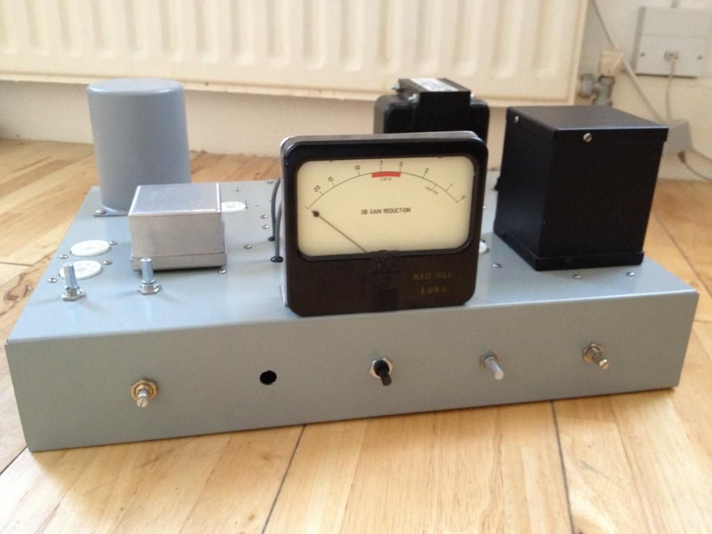
I also love the look of the BA-6A and decided to mimic it as closely as I can. I know cloning the look of a piece of kit is frowned upon on this forum, but I'm not doing this to impress a client, it's just for my own amusement!
I'm pretty new to tube electronics -the only other thing I've built with tubes is an RCA BA-2 pre amp (also with the original transformers and NOS RCA tubes), so progress has been slow. I've been asking all sorts of newbie questions over on this thread: http://www.groupdiy.com/index.php?topic=47096.0 and have been learning a lot.
Again, inspired by DaveP, I'm aiming to document the build with photos as I go. Hopefully this will be fun to read (come on, we all love a bit of gear porn, right?). As I'm quite new to this, please shout out if you spot me doing anything wrong, or can think of better ways of doing things!
============================
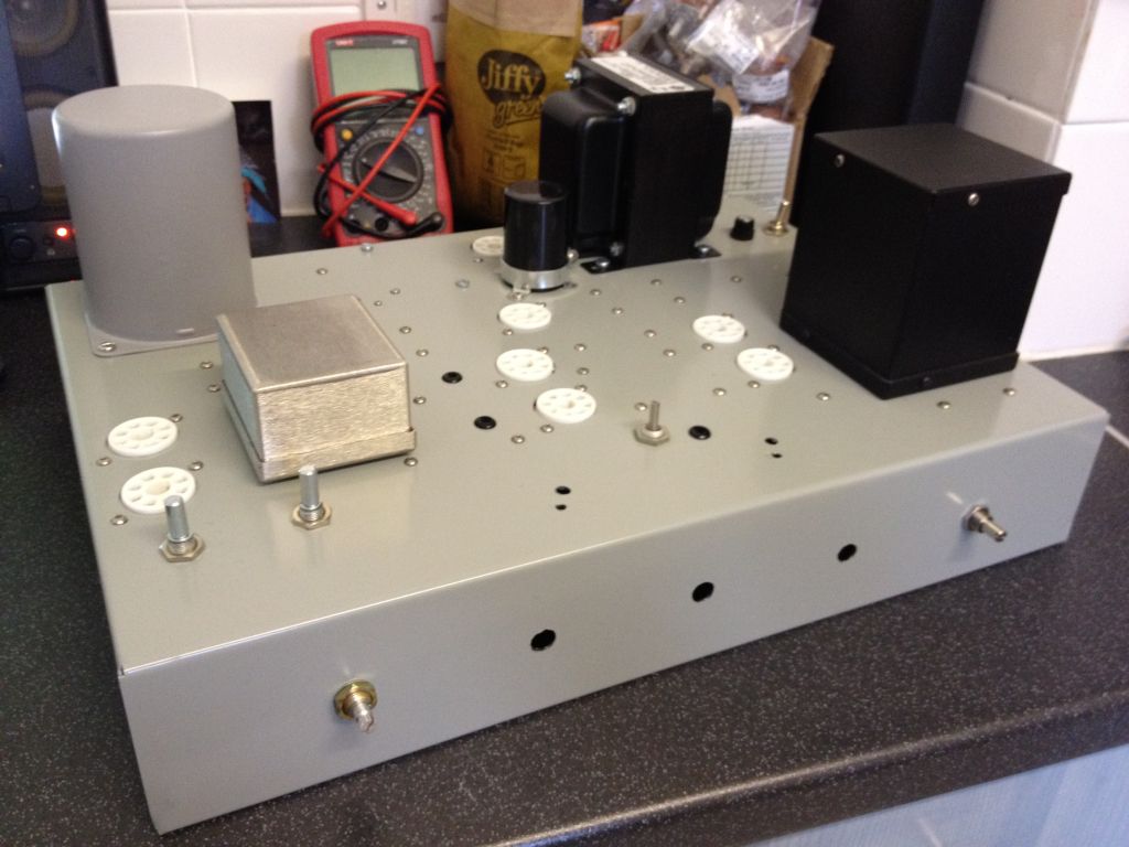
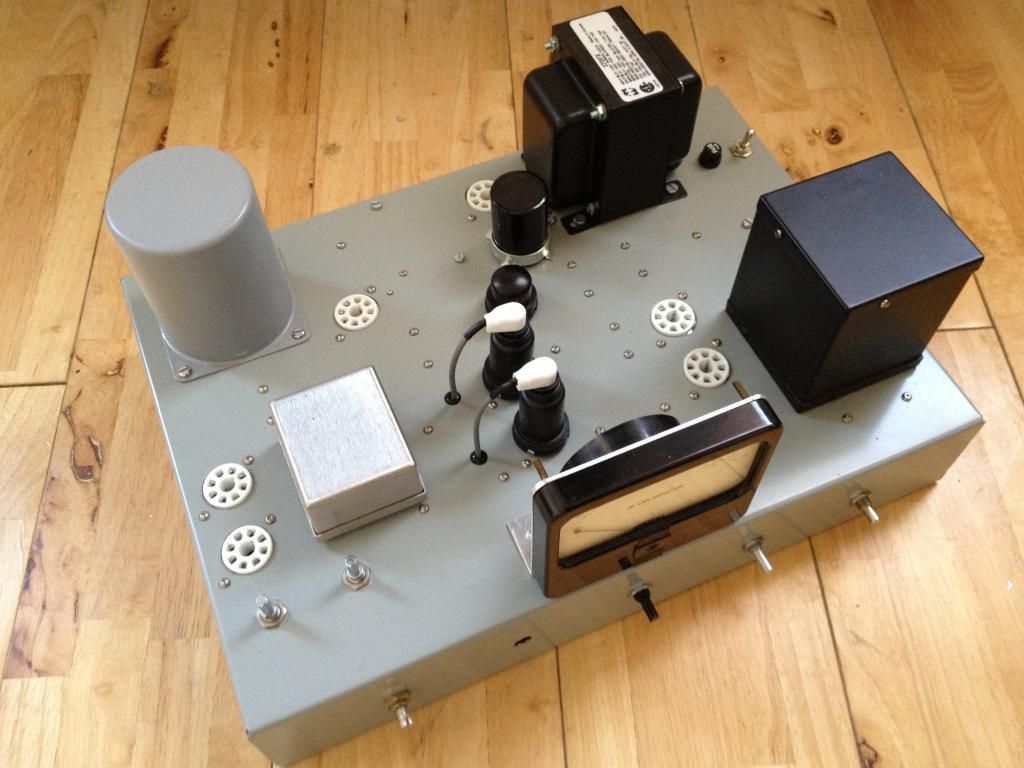
I'm using a standard Hammond steel chassis for the build. After about a week of drilling I finally ended up with this:
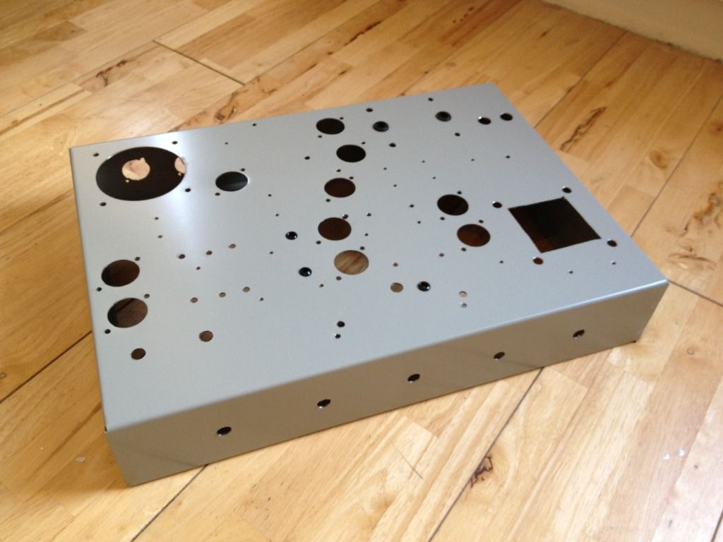
I'm pretty inexperienced when it comes to metal work, but I'm pleased with this. I used a hole punch for the tube sockets, and they came out great -never again am I going to use a step drill! Perfect circles with no burrs or anything!
After drilling the (many many) holes, I started on the power supply.
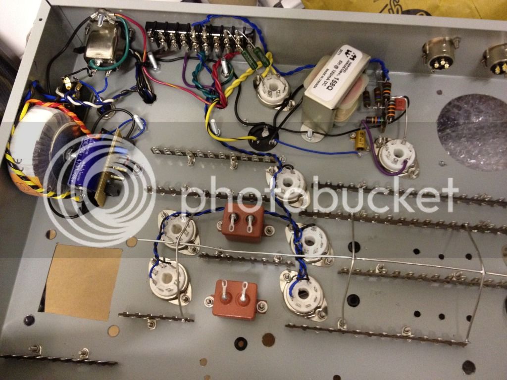
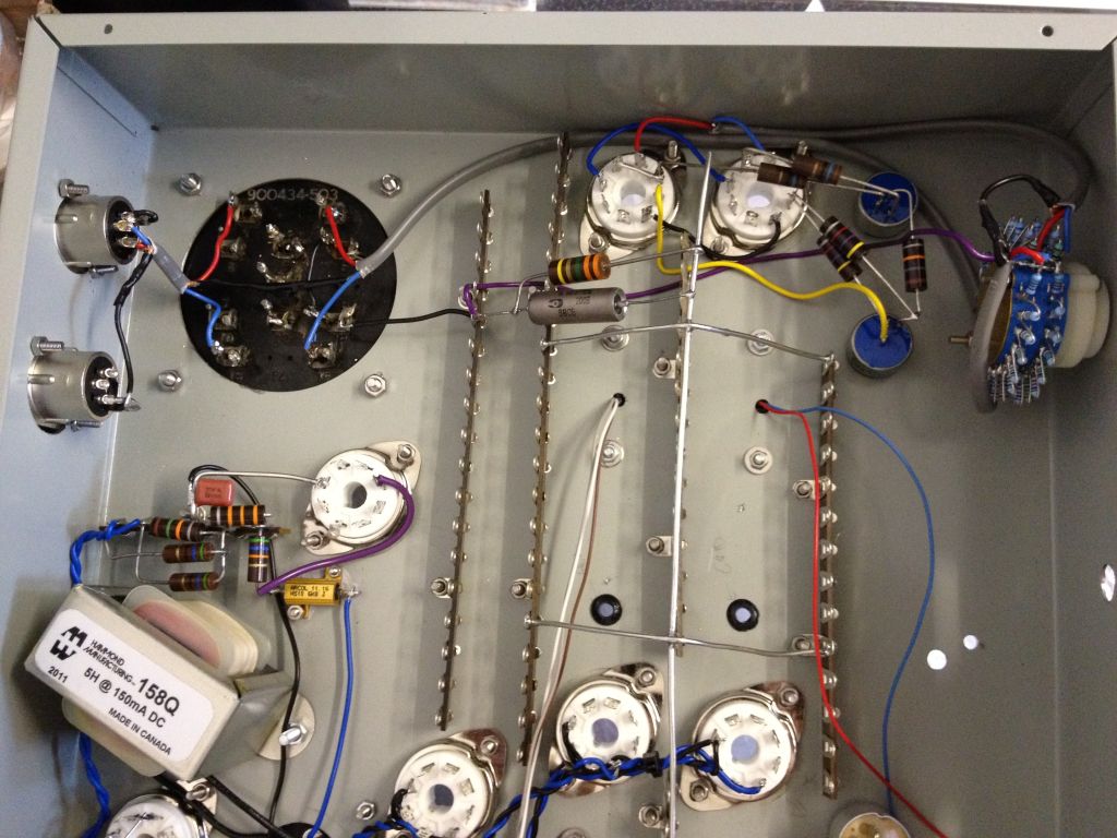
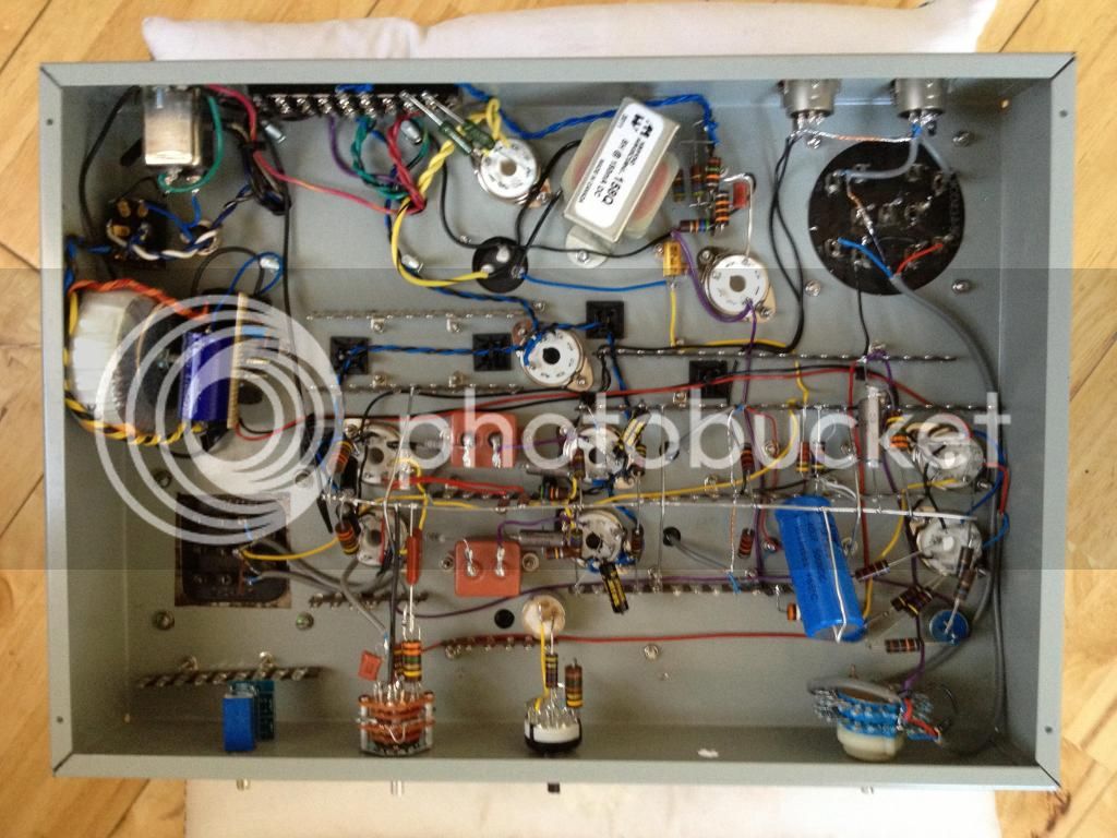
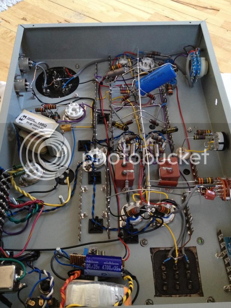
I've copied the original schematic entirely for the power supply -except the DC circuit. Rather than use a choke as per the schematic, I decided to build a circuit based around a LM317 chip to give me a regulated 6.3VDC supply to the 6SK7 tubes. You can see it on the left of the picture hooked up to the separate toroidal transformer.
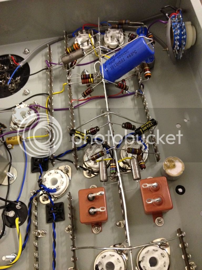
The only other difference from the schematic is that I've used resistors between the transformer and the rectifier tube. This is so I can a) drop the B+ if I need to and b) prolong the life of the tube (I believe it allows an even current across it)
I tried to do the AC heater wiring as neat as possible. They're wound very tightly with a drill and wired in phase, which should allow the push pull circuitry remove as much hum as possible.
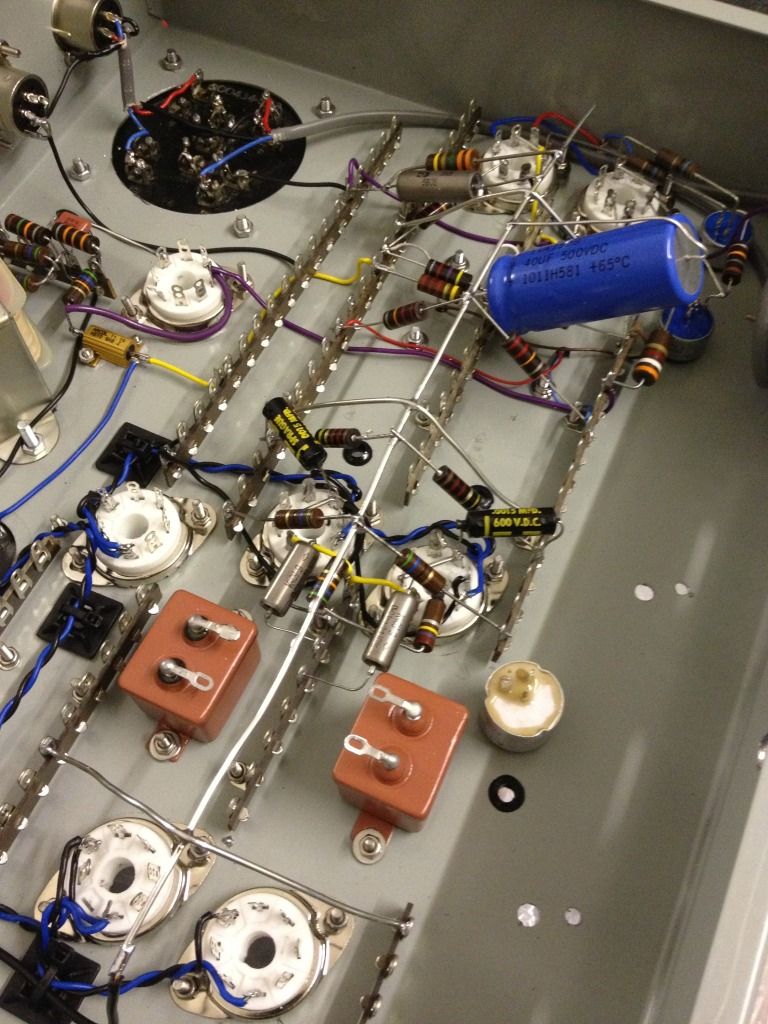
After hooking it all up - voila:
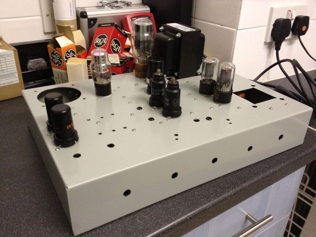
All tubes getting what they need! You can really see it in this photo but the 0D3 glows a rather fetching purple, which is nice.
That's all I've got so far, I'll try and update this as often as possible.
I also love the look of the BA-6A and decided to mimic it as closely as I can. I know cloning the look of a piece of kit is frowned upon on this forum, but I'm not doing this to impress a client, it's just for my own amusement!
I'm pretty new to tube electronics -the only other thing I've built with tubes is an RCA BA-2 pre amp (also with the original transformers and NOS RCA tubes), so progress has been slow. I've been asking all sorts of newbie questions over on this thread: http://www.groupdiy.com/index.php?topic=47096.0 and have been learning a lot.
Again, inspired by DaveP, I'm aiming to document the build with photos as I go. Hopefully this will be fun to read (come on, we all love a bit of gear porn, right?). As I'm quite new to this, please shout out if you spot me doing anything wrong, or can think of better ways of doing things!
============================
I'm using a standard Hammond steel chassis for the build. After about a week of drilling I finally ended up with this:
I'm pretty inexperienced when it comes to metal work, but I'm pleased with this. I used a hole punch for the tube sockets, and they came out great -never again am I going to use a step drill! Perfect circles with no burrs or anything!
After drilling the (many many) holes, I started on the power supply.
I've copied the original schematic entirely for the power supply -except the DC circuit. Rather than use a choke as per the schematic, I decided to build a circuit based around a LM317 chip to give me a regulated 6.3VDC supply to the 6SK7 tubes. You can see it on the left of the picture hooked up to the separate toroidal transformer.
The only other difference from the schematic is that I've used resistors between the transformer and the rectifier tube. This is so I can a) drop the B+ if I need to and b) prolong the life of the tube (I believe it allows an even current across it)
I tried to do the AC heater wiring as neat as possible. They're wound very tightly with a drill and wired in phase, which should allow the push pull circuitry remove as much hum as possible.
After hooking it all up - voila:
All tubes getting what they need! You can really see it in this photo but the 0D3 glows a rather fetching purple, which is nice.
That's all I've got so far, I'll try and update this as often as possible.
")