Clamping For Two-Stage Opamp

GroupDIY Audio Forum

Help Support GroupDIY Audio Forum:

This site may earn a commission from merchant affiliate links, including eBay, Amazon, and others.

Samuel Groner

Well-known member
Joined
Aug 19, 2004
Messages
2,940
Location
Zürich, Switzerland
Hi

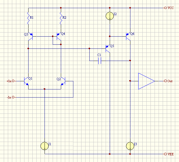
Consider the following classic two-stage Miller compensated opamp topology:
miller-opamp.gif


As shown this architecture suffers from polarity reversal during and slow recovery from clipping; in addition to this, Q6 will draw large currents from Q5 during saturation which might cause failure.

To solve this, a clamping diode in parallel with C1 is usually added. However, simulation and actual measurements show that the presence of this diode causes a substantial increase in distortion of the second stage (Q5/Q6). For typical values of C1 (100 pF) this increase is about 10x (of course this is only revealed if sufficient care to input stage and output buffer is given); presumable cause is diode capacitance modulation.

A resistor in series with Q5 collector solves the failure problem and somewhat aids recovery; polarity reversal is untouched though. Any ideas for another clamping circuit which would address all issues while not causing degraded distortion?

Samuel
 
If you could accurately track the voltage at Q5 base, you could put a clamp there I suppose.

If you put a current sense R in the emitter of Q6, and have a resistor in the collector which dominates the current swing of Q6 (the buffer has enough composite beta for given loads that the majority of the curent is in that internal loading R), you could make a current limiter that would turn on and pull away Q1 collector current from Q5 and prevent Q6 from saturating that way.

The current sense R could be bypassed with a C to allow higher slewing currents momentarily.

Not sure what all of this would mean to the stability margin when close to limiting action. And you lose some low-frequency open-loop gain with that resistor loading on the big-swing node, but people would argue that you don't need and may not even want that for audio amps.
 
What diode (/model) are you using? I would expect that a 100p cap would swamp the capacitance modulation of a low-current low-capacitance diode.

Does a small series resistor help?

JDB.
[pity that the swing is too large for a diode-connected transistor]
 
[quote author="jdbakker"]What diode (/model) are you using? I would expect that a 100p cap would swamp the capacitance modulation of a low-current low-capacitance diode.
[/quote]

That is a little strange isn't it---looking at an old process D1 curve, the 1N914-ish parts show a C going from 1.5pF at zero volts to just under 1.25pF at 60V reverse.

I know 1A power diodes like the 400X series are much worse (one guy was using one as a varactor in fact), but then you don't need those here.
 
I'm somewhat puzzled by the magnitude of the effect myself but things are very repeatable and were at least in simulation checked for many different designs.

For simulation I used a 1N1914B, for real world a 1N4148. A larger part such as 1N4004 gave much worse results in simulation as expected.

Does a small series resistor help?
Didn't try that--why would you expect this to help?

Samuel
 
I suspect the National Semi data is off---it doesn't reconcile well with the standard power law model of diode capacitance.

Another approach that appears to work, assuming the capacitance modulation is as bad as sims say: put a ~Baker clamp on Q6. You could just use a schottky, but the leakage current is usually a nuisance, so two 914-ish diodes would be used. Since the diode tied to the collector is now mostly loading the output node rather than being an overall part of the integrator capacitance, the effect is greatly reduced---I guess by about the current gain of Q5.

But now you have to limit the current in Q5, since it is otherwise just limited at its beta times the input diff pair tail current---possibly just a resistor in the collector, bypassed by a small C so it doesn't have a large bandwidth-reducing and compensation-fouling Miller effect.

I like this idea a lot more than my earlier suggestions. You are not cutting into the output swing, for one thing.

EDIT: Sims of a somewhat idealized configuration, using ideal current sources, with the baker clamp show the expected reduction. 3k in the collector of Q5, bypassed with 100pF looks about right for its protection and doesn't mess anything up otherwise.
 
[quote author="bcarso"]I suspect the National Semi data is off---it doesn't reconcile well with the standard power law model of diode capacitance.[/quote]
Vishay Telefunken (MCL4148) has it as [email protected] to 1.1pF@40V; Fairchild (1N4448) is 0.87pF@0V to 0.82pF@15V. Not that I have many other candidates, but are we sure it's capacitance modulation related?

[quote author="Samuel Groner"]
Does a small series resistor help?
Didn't try that--why would you expect this to help?[/quote]
Decoupling (for lack of a better word) the varicap from the rest of the circuit; 10 Ohm should be enough to swamp its capacitive effects, especially with the 100p in parallel. But maybe my brain is too much in RF mode these days.

That Baker clamp sounds interesting. OTOH, low leakage Schottky diodes do exist, especially if you don't mount the assembly in an oven (and keep some space between the diode and the output stage). The 1N5711 has ~8nA leakage at room temperature, increasing to ~200nA at 75C.

JDB.
 
A more recent National Semi book I dug out, I believe the last one (1989) before they stopped bothering with the process data, shows something more realistic-seeming for the 4148 D4 process: about 1.7pF at close to zero dropping to 1.0pF at 14V reverse. The Spice model shows still more C modulation than this, with ~0 bias closer to about 3.3pF.

For what it is worth, a sim of the VAS alone with ideal I sources and the baker clamp with 1N914B parts, driven with 2uA p-p and with a 100pF feedback C, shows about 3.6ppm distortion that is mostly 2nd at 1kHz. With the conventional diode across the C, it is more like 105ppm. Each example is loaded with 100k on the output.

These results are obviously neglecting some other effects and are fairly decent for the conventional approach. I am still surprised at the predicted magnitude of the effect. One thing to note is that these are not particularly low leakage diodes, so there is a conductance term in the midst of the C modulation. That is also rendered correspondingly less important by the baker clamp strategy.
 
Thanks for the suggestions, will need to look at them in detail later.

Today I run some measurements (at 60 dB loop gain) on a design with a 33 pF compensation capacitor: diode_capacitance_modulation.pdf

With a 1N4148 distortion shows up above 1 kHz; without clamp distortion is unmeasurable (BTW, this is a result which I've not seen on any IC opamp so far). Just for fun I run another sweep with a varactor diode--now distortion becomes measurable above a few dozen Hz! As it has exactly the same slope as distortion from the 1N4148 I think it is pretty clear now that capacitance modulation is the culprit. The noise floor of the measurements varies as the added capacity of the clamping diode reduces the bandwidth of the amplifier.

I'm surprised that I've never seen this issue to be mentioned. Seems like low-distortion amplifier synthesis is still in its childhood...

Samuel
 
No filters, i.e. 10 Hz-500 kHz. The opamp GBW (divided by 1000) sets the bandwidth, as seen in the "noise floor" sweep which is just a THD+N measurement at -20 dBu divided by 100. The other plots are at +20 dBu.

Samuel
 
Im dealing with this same issue right now, sort of. Ive got a new ultra-low distortion opamp on the bench that is overall woring very well except for overload recovery. there are some siginificant diferences in the details of my circuit, but similarly the really disturbing event is on the positive side. it starts oscillating coming out of saturation, and even though the amp is unity gain stable, it doesnt stop. I also find that the traditional diode in parallel with the miller cap ruins distortion performance.

one thing to think about: I found that If Q5 is switched to NPN the polarity reversal problem might be solved without a diode.

Brute force:
like brad suggested I have looked at clamping Q5 base -- by turning on a "CCS" to the positive rail when the output voltage gets above a threshold (in my case, when it gets close to the base voltage of a cascode transistor in the collector of Q6). this is actually a feedback loop and tends to want to oscillate as well, but by compensating the clamp circuit such that it turns off slower than it turns on, it works. a small C in the base of the "CCS" clamp transistor is charged directly by the collector of the sense transistor, discharged by a large value resistor to the positive rail.

I havent looked yet to see if the collecor capacitance of the clamp transistor is ruining the high frequency distortion at all.

mike p
 
My interest in, and rediscovery of, 41 years later, the Baxandall superpair, stemmed from the realization that the variable* output C of crucial internal stages with big voltage swings was one of the most significant open-loop distortion mechanisms. Usually the offending C is collector-base, but with these clamps we get the diode contribution, or other ones from the selected device.

If you are switching on a CCS, you can make one of those using Baxandall's idea and have the equivalent output C very small**. However, whether it turns on and off quickly enough for your needs is another issue, and many of these circuit additions cut into available voltage swing.


* most authors say the nonlinear capacitance, but although it always is for diodes and three-terminal sand-state devices to date, just the variation with voltage is sufficient for it to be a distortion generator.

EDIT: ** and being small, the variation in it becomes correspondingly less important.
 
one possible advantage of the brute force method is you can control the clipping beyond being well-behaived, you can actually make it soft-clip, and vary the symmetry, which might have some subjective benefit.

the voltage at Q5 base stays mostly constant, the nonlinear capacitance of the diode is a problem because the other side of the diode is connected to the output node, which changes voltage like crazy. if you use a clamp to the rail, the clamp Q sees very little voltage change. I predict about 300pA pk-pk current flowing in an off-state clamp. this is with 3pF CB capacitance.

in simulation, putting a small ideal C of 3pF to ground off Q5 base shows almost exactly the same behavior as the simulated unbiased BJT collector. in both there are lots of harmonics in the current waveform. the voltage across the cap doesnt support this, a glitch? the distortion performance of the amp doesnt seem to be spoiled. putting more capacitance to ground off Q5 base does not destabilize the amp. what is the effect of lots of stray C at this node?

mike p
 
Back
Top