Console signal flow, input cards, general discussion on API styled DIY mixer

GroupDIY Audio Forum

Help Support GroupDIY Audio Forum:

This site may earn a commission from merchant affiliate links, including eBay, Amazon, and others.
I sent my pdf docs to boji.  They were to big to attach.  The docs are full scans of the blueprints and are therefore slow opening and exceed the size of my graphic card to mange quickly.  I'm hoping to scan more info I have on the API 2488 I own.   

Perhaps we can get boji to post these and some working schematics can be created.  I always hand draw a circuit when working on a problem in the modules and then proceed to loose it after I fix things.

Michael
 
Any chance of seeing some pictures of the metal work? I have been thinking about doing something like this myself. Don't forget that the metal work is a fun part of the DIY process! :)
 
Oh Wow this is gonna get awesome  :D

You know as soon as I see it I can't help thinking "wood sides now, wood sides!"...haven't read
through it so I don't know if it's been mentioned but first inner response ;)
 
dsoukup-
"Any chance of seeing some pictures of the metal work?"
I feel like it was premature to post a picture at all. Give me time. When I can stand back from it and be only thinking about signal flow and component choices, I'll post more picts.

"Don't forget that the metal work is a fun part of the DIY process!"
If you want fun, I can think of better things to do with your time.  ;D


Livingnote-
Thanks for the support! I have yet to decide on the sides- I may have a guy tack-weld threads to the inside of a clean endpiece, and cap the sides in polished aluminum. That would make it a magnet for scratches, so I dunno yet.
 
Thanks Tubemooley.    I've had these diagrams and others for a long time.  I hope people enjoy looking and redrawing them.   

Circuit diagrams will help boji so if we post some drawn out easier to read ones, it would be great.  I'll take some pictures of my board if anyone is interested in PC cards and backplane bus distro. 

The pdfs were scanned by InDox and are very slow to open.  Not sure why but what I did was opened them in Preview on a Mac and save them as a jpeg, and they work better,  that is they open faster.   

Now to watch the last Lost.
 
Again thanks Abby and Tv.
Page 1 schema revised to 3.4.1 and replaced 05/24/10

The fader is not properly connected. Input --> Top, output --> wiper.
- Fixed

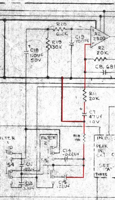
There's something wrong with the filter; the 13k res should not go to gnd. It should go either to the output of the 2520 (most likely) or to its negative in.
See pict below, it looks like it is going to the 2520's neg in, but neg in also gets grounded.

And the switching of Filt 1 doesn't make much sense.
No it diddn't, sorry. I think I have fixed it.

There's also something wrong with the pre-fade echo feed; the 4k7 res, in conjunction with the 1k small fader introduces 16dB+ of attenuation, which, I'm sure, is not intentional. Maybe it's just the value of the resistor that should be lower, I don't know.
I  see 4k7 in conjunction with 5k pot. Is this correct?


13kgnd.jpg
 
The 528c or 536 diagram which is easier to read, is made of 2 cards (PCBs).  1 side has a 15pin and 10pin.  The other side is an 18pin edge connector for plugging into the back plane bus ,in out connects. 

The wiring diagram is the key to understanding things.

the preamp out from the transformer, goes to the patchbay to the 550EQ input.  The 550EQ output goes to pin 13 on the 15pin connect.  Pin14 is the prefader output and send to the top of fader.  Pin 15 is the output from the fader back to the 536 input that feeds into the filter switch. 

You see all of this in the Wiring Diagram on the lefthand side of the picture.

I have some hand drawn examples of the filter which has three curves from 2 switches marked Flt1 and Flt2.  If you don't push flt1 or 2 you feed the fader into the 1Uf cap , C18. 

If you push flt 1 you go fader out to .1 cap to .01 cap to C18 ,  with a 15k to ground between .1 and.01 cap. 

If you push flt 1 you go fader out to .22 cap to .02 cap to C18 ,  with a 15k to ground between .22 and .02 cap

If you push flt 1 and 2 you go fader out to .22||.1 cap to .02||01 cap to C18 ,  with a 15k to ground between the Parallel caps

This then .32 to .032 since the caps add creating 3 curves for lowend roll off.
 

Attachments

  • Wiring diagram.jpg
    Wiring diagram.jpg
    170.5 KB · Views: 309
I have some hand drawn examples of the filter which has three curves from 2 switches marked Flt1 and Flt2. 

If you don't push flt1 or 2 you feed the fader into the 1Uf cap , C18 to the + input via 6.2k R20. 
If you push flt 1 you go fader out to .1 cap to .01 cap to C18 ,  with a 15k to ground between .1 and.01 cap. 
If you push flt 2 you go fader out to .22 cap to .02 cap to C18 ,  with a 15k to ground between .22 and .02 cap
If you push flt 1 and 2 you go fader out to .22||.1 cap to .02||01 cap to C18 ,  with a 15k to ground between the Parallel caps
equals then .32 to.032 since the caps add, creating 3 curves for low end roll off.

The drawing on the bottoms shows the signal flow: 
The preamp out from the transformer, goes to the patchbay to the 550EQ input.  The 550EQ output goes to pin 13 on the 15pin connect.  Pin14 is the prefader output and send to the top of fader.  Pin 15 is the output from the fader back to the 536 input that feeds into the filter switch.

Sorry about the double post.  I'm still learning this stuff


Attachments

  • filters small.png
    filters small.png
    259.7 KB · Views: 300
3.4.1 shows filter switching correct, and fader correct.  I think I would include the 550 module .  Maybe as a function block showing its input and output going to the channel on off switch, which is how most original API's were put togeother. 

Modern consoles usually have inserts after the EQ,  These API's have the insert after the Mic/Line Preamp out(tx balanced) before the EQ.  The Eq is used as a buffer  to the fader and Channel on/off switch(S10).    In a 550 EQ the in/out switch bypasses eq but is not True bypass.  You have a input 2520 and an output 2520 always in the channel path. They buffet the fader from the insert patch point. 

Modern consoles have a mic trim and a line trim.    These API's have the fader feeding A2 and A2 feeding the Mix (Level R51C) before the Pan to L/R mix.  The Level control acts like a trim pot for keeping your fader at reference level, while trimming with the concentric level control stacked on top of the Pan.  These were designed to max out your levels to tape and then trim down mix level to balance the mix to avoid tape hiss, while keeping fader at cal.

Later API's built in the 90's dont have this.  They use line trim for that function I believe.
 
Thank you fazer for the confirmation on the 3.4.1 revision.
And thank you for the mixer insert history lesson and filter drawings!
This certainly helps clear up some confusion on my part.

If you don't mind, I have another question on what something is doing in the schema:

Referencing JR, in responding to an argument for unbalanced signal:
"In case I wasn't clear.. with the possible exception of some old school class A tube gear, it doesn't require more active circuitry to differential an input.  Further true balanced interfaces are not beneficial for modest length paths.

As long as both + and - audio signal wires are shielded and not contaminated with ground noise currents a simple differential receiver will give excellent signal purity.

We may be confused about terminology. I am not talking about dual active opposite polarity signal feeds. I am only talking about treating + and - audio lines the same, and not contaminating the - audio line with shield noise and ground currents between chassis."
http://www.groupdiy.com/index.php?topic=38549.msg477818#msg477818

Active opposite polarity (differential?) balanced line inputs...That means there are passive differential line inputs and these have a tendancy to not contaminate the signal? I guess I'd like to understand the difference between active and passive (forgive me if the answer ought to be obvious) signal feeds. On the 536, the input card gets this treatment:


What are the diodes on the line input doing? Is this any part of what makes it 'active'? Are they there to remove extraneous DC from the signal?
What if 16+/- was not connected to the input, what would happen to the signal?  
 
I think I know the answer for this one.

The diodes are used to protect the input. If the line signal should be above +16V or lower than -16V the diodes will clip the signal.

By doing this, the input stage will not be damaged because of transients or some extreme signal conditions.

To be clear, the diodes CR9 and CR10 are connected to +16V, and will conduct if the voltage is higher than around +16.5V.

The same with CR7 and CR8, but if the voltage goes lower than -16.5V.

I cannot answer your question on the active  / passive, sorry.

Hope this helps.
 
crevil is correct  on the Diodes as a protection to the input.

As far as Balanced input/outputs go.  Transformers being passive have the ability to be wired in such a way to allow a break from ground between 2 points.  Say an Audio mix room from a Video Switching room.  They are located a distance from each other and have a ground potential difference which can create hum and noise or a ground loop.  Passive transformers work really well in this example.

Within a console, you have a very short path from mic pre output to equalizer input, so it could run unbalance and usually is in most modern consoles. 

If there is an insert between the preamp and the Equalizer it can be balanced or unbalanced, active or passive.  Transformers were used in older consoles and active balanced amps are used in more modern consoles.  Some patch points can be a mixture of both. 

The Preamp out on the patchbay of my API uses a transformer to go out to the bay as a balanced out that ground the lo side to the unbalanced input lo side, of the 550 EQ.  Its kind of backwards from the way things are done today. 

The normal config for an active system would be use unbalanced output from an opamp or discrete opmap,  to a active balanced input of a Diff opamp.  Usually there is adequate noise rejection for a line level signal in a short run in the same room with the console.

Active balance is cheaper to implement than buying a good sounding transformer.

Other people may want to chime in here to help. And also to correct anything explained that seems misleading.


boji said:
There's something wrong with the filter; the 13k res should not go to gnd. It should go either to the output of the 2520 (most likely) or to its negative in.
See pict below, it looks like it is going to the 2520's neg in, but neg in also gets grounded.
Agreed. Not very sophisticated according to current standards, that's why I've had some doubts.
There's also something wrong with the pre-fade echo feed; the 4k7 res, in conjunction with the 1k small fader introduces 16dB+ of attenuation, which, I'm sure, is not intentional. Maybe it's just the value of the resistor that should be lower, I don't know.
I  see 4k7 in conjunction with 5k pot. Is this correct?
Yes, should be much better that way.
 
API's are not very sophisticated.  That filter is an add on 6 db/octave.  I don't use them much.    It's the micpre,  with the iron transformers that have some weight to the sound.  Only 2 2520 amps to the mix.  Its a great sound. 

There is a friendly top end to these things.  But the filters are passive and simple.    People build the summing amps to mix outside the box, because they like the sound better. Its also in vogue to do now.

I opened my 528C input.  It has 39k on cue and echo to bus and 47k on the channel to mix buss and subs 1-8 .    The Sum Amps have gain to drive that signal level right.  so the gain is Rf resistor on sum amp output to - input,  with 39k being R1 for that channel sum to buss and input to the - input on the sum amp.     

2520s  put  1w of power into 600 ohms.  Isn't that 30dbm?

 
Hello again,

schem asks for 250uf @4v at the output of the op-amp.

I'm trying to source one and I found 
http://www.mouser.com/ProductDetail/Vishay-Sprague/715P22256JD3/?qs=sGAEpiMZZMvCt%252bwg%252braTuvW0YsKHLWlohro4WlUsabA%3d
an 'orange drop' cap 220pf 5% 500v, with a "load life" of 500 hours.

Few questions:
If I can't find a cap that meets the schema is it
1) always better to go with a higher value?
2) when calling for say, a 4v cap, is it ok to go with something higher? How high is too high?
3) What does 'load life' mean? is that cap life or hold charge life? 

And lastly if you want to recommend a better choice I am of course all ears.
I'm trying to use WIMA's where I can.

Thanks
 
Boji, you are out of range by a big margin there!! 220pF is a million times smaller than 250uF.  ;D
I've used the Vishay BC caps http://uk.farnell.com/vishay-bc-components/2222-021-36221/capacitor-220uf-25v/dp/1165468
They don't have to be that higher voltage, 6.3 or 10v will be fine.
 
fazer said:
API's are not very sophisticated.   That filter is an add on 6 db/octave.   I don't use them much.    It's the micpre,   with the iron transformers that have some weight to the sound.  Only 2 2520 amps to the mix.   Its a great sound.   
I think there may be slightly more than 2 2520's to the mix, dependent on the desk. 2 for the 548 channel, 2 for the 550A EQ (no hard bypass, and always in circuit unless overpatched), 1 in the ACA and 1 in the master fader VCA, and then 1 in the Mix Booster output.
This is from memory so may be out by 1.... ;D
 
Back
Top