Matador
Well-known member
I'm trying to wrap my head around the design procedure for push-pull class AB1 power amp stages.
I'm thinking about how to design using a specific transformer:
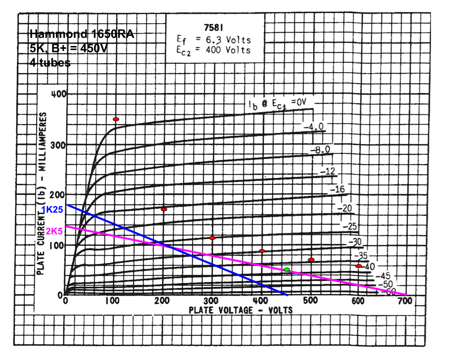
Hammond 1650RA, 5K @ 100W
So if I understand correctly, in a push-pull configuration, each tube would see one half of the output impedance in the class A portion of the output characteristic, which it will see until one of the tubes cut's off, at which point the impedance drops by 1/4 (since turns ratio is half, impedance is 1/4).
Starting with a 7581A tube, and placing these AC load lines on the plate curves, assuming B+ of 450V, gives this result:
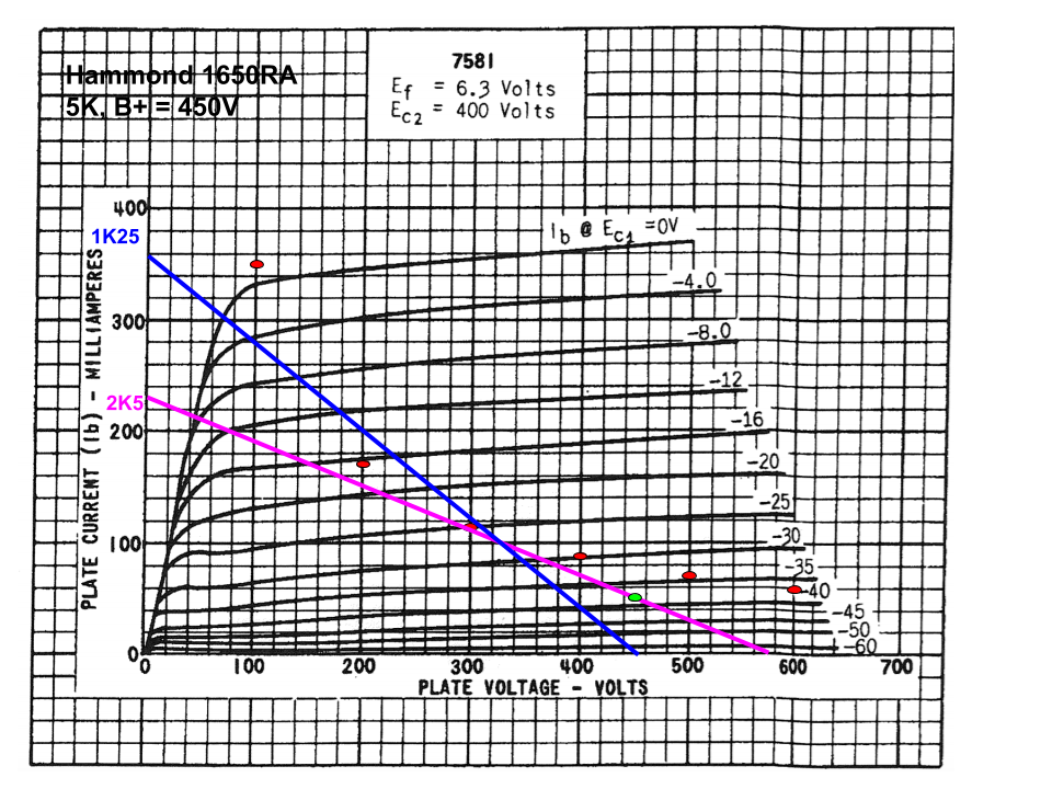
The data sheet suggests a bias point of -37V @ 55mA with a plate-to-cathode voltage of 450V, which is the green point on the class A load line in purple.
So this seems to line up exactly with the datasheet recommendations. Peak current is roughly 300mA (where the class B load line crosses the 0V grid curve) at a plate voltage of about 70V, so power output (per RDH) is roughly ((B+-Vamin)*ipeak)/2, which in this case is ((450-70)*0.3)/2 = 57 watts for a pair of tubes, which again agrees almost exactly with the operating point specified in the datasheet.
What I can't wrap my head around is doing this with parallel tubes per side. In theory, I should be able to consider push-pull arrangement of parallel tubes as the same as a plain push-pull arrangement of two tubes, with the group of tubes acting as a single composite tube.
If I use two 7581's in parallel, then with the same grid potential, plate-to-cathode potential, and the same screen potential, I should flow exactly twice the current. Thus if I relabel the plot above with the currents doubled then the analysis above should be exactly the same, yes?
In other words, if I replot these load lines on a new 'composite' curve with the plate current doubled, I get this:
The new ipeak is 340mA, the new plate minimum is 40V, so output power is ((450-40V)*0.34)/2 = 70W. Not double by any means!
In order to restore the look of the first image above, I need to halve the impedance of the output transformer. This superimposes the original load lines on the first image, however the plate currents are doubled. The power output would be ((450-70)*0.6)/2 = 114 watts for a quad of tubes.
In order to do this, I would need an output transformer rated for 2.5K primary impedance, or, I think I would attach an 8 ohm load to the 16 ohm tap, which should reflect half of the rated primary impedance, correct?
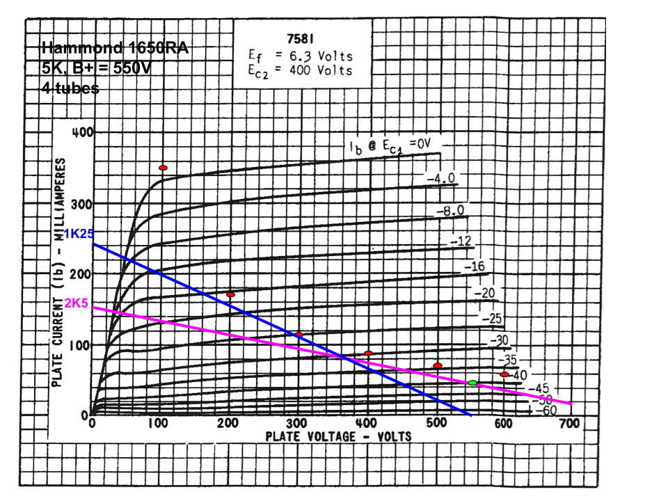
In the alternate, it looks like I could increase the B+ voltage to move the load lines to the left, and pick a different bias voltage. Increasing the B+ up to 550V, gives a new idling point at -40V. ipeak increases to 440mA, at a plate minimum of 50V, which is )(550-50)*0.44)/2 = 110 watts, roughly equal to the power output of the half-impedance transformer.
Am I thinking about this correct? If there a pro/con for each approach?
I'm thinking about how to design using a specific transformer:
Hammond 1650RA, 5K @ 100W
So if I understand correctly, in a push-pull configuration, each tube would see one half of the output impedance in the class A portion of the output characteristic, which it will see until one of the tubes cut's off, at which point the impedance drops by 1/4 (since turns ratio is half, impedance is 1/4).
Starting with a 7581A tube, and placing these AC load lines on the plate curves, assuming B+ of 450V, gives this result:
The data sheet suggests a bias point of -37V @ 55mA with a plate-to-cathode voltage of 450V, which is the green point on the class A load line in purple.
So this seems to line up exactly with the datasheet recommendations. Peak current is roughly 300mA (where the class B load line crosses the 0V grid curve) at a plate voltage of about 70V, so power output (per RDH) is roughly ((B+-Vamin)*ipeak)/2, which in this case is ((450-70)*0.3)/2 = 57 watts for a pair of tubes, which again agrees almost exactly with the operating point specified in the datasheet.
What I can't wrap my head around is doing this with parallel tubes per side. In theory, I should be able to consider push-pull arrangement of parallel tubes as the same as a plain push-pull arrangement of two tubes, with the group of tubes acting as a single composite tube.
If I use two 7581's in parallel, then with the same grid potential, plate-to-cathode potential, and the same screen potential, I should flow exactly twice the current. Thus if I relabel the plot above with the currents doubled then the analysis above should be exactly the same, yes?
In other words, if I replot these load lines on a new 'composite' curve with the plate current doubled, I get this:
The new ipeak is 340mA, the new plate minimum is 40V, so output power is ((450-40V)*0.34)/2 = 70W. Not double by any means!
In order to restore the look of the first image above, I need to halve the impedance of the output transformer. This superimposes the original load lines on the first image, however the plate currents are doubled. The power output would be ((450-70)*0.6)/2 = 114 watts for a quad of tubes.
In order to do this, I would need an output transformer rated for 2.5K primary impedance, or, I think I would attach an 8 ohm load to the 16 ohm tap, which should reflect half of the rated primary impedance, correct?
In the alternate, it looks like I could increase the B+ voltage to move the load lines to the left, and pick a different bias voltage. Increasing the B+ up to 550V, gives a new idling point at -40V. ipeak increases to 440mA, at a plate minimum of 50V, which is )(550-50)*0.44)/2 = 110 watts, roughly equal to the power output of the half-impedance transformer.
Am I thinking about this correct? If there a pro/con for each approach?