Discrete preamp design

GroupDIY Audio Forum

Help Support GroupDIY Audio Forum:

This site may earn a commission from merchant affiliate links, including eBay, Amazon, and others.
Typically for fixed bias operation, you pick a collector current, then the resistor is selected based on the beta of the transistor you are using. For example, for a beta of 200, for a 1mA collector current you need ~5uA of base current. Since you want the transistor to always be on, then you need at least a VBE drop above ground, so the base resistor = (9-0.7)/5uA ~ 1.6Mohm. For a beta of 100, then it drops to half (about 800K). Not 4.7KOhms like you are using. With 4.7K you are driving ~2mA into the base, which means at a beta of 200 the transistor wants to sink 400mA. :O
 
Food for thought..

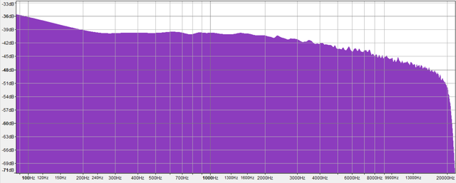
Meanwhile, here's the frequency response plot measured using white noise :

pre-freqresponse.png


EDIT : it seems to have an exaggerated low end below 150-200Hz.. just what I thought I was hearing when playing program material.

EDIT 2 : now, before ordering more of these transistors (BC547 general purpose amplifier) and Veroboard I noticed there are A, B and C versions available.. in the component it says BC547 B 331, is this the B version I'm using?
 
Last edited:
Never forget that bipolar transistors are CURRENT amplifiers, not voltage, although the effect may look similar on the scope. With a resistor in the collector to the power source, the current changes the output voltage, and the input current changes accordingly. The gain varies with the current.
With a constant current source, instead of a collector resistor, the input current remains (nearly) constant. Most signal sources are happier with this.
Without an emitter resistor the gain is the ratio between the devices intrinsic emitter resistance and the collector to power supply resistor.
Using a free circuit analyzer like LTspice you can discover a lot of things without burning up parts. Much faster and easier. Many youtube videos.
Have fun!
Also dig into the part datasheet to get a grasp of the devices capability.
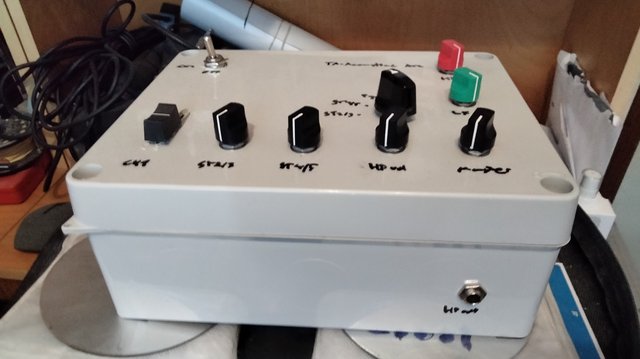
Yeah I was thinking of hacking it into one of my DJ mixers which is currently passive, as it could benefit from a headphone amplifier.

IMG-20240315-154534.jpg


I did some tests yesterday but I've had the flu for a couple of days now.

Maybe supply it with 12V using a regulator or a suitable resistor.
 
Alright, just ordered some BC547B transistors, NE5534 opamps (for future use), trimmers, stripboard and turrets.

I have loads of resistors and capacitors from my previous build so I need to put them to use before the caps go bad.

Meanwhile I'll keep testing and experimenting with the breadboarded circuit.
 
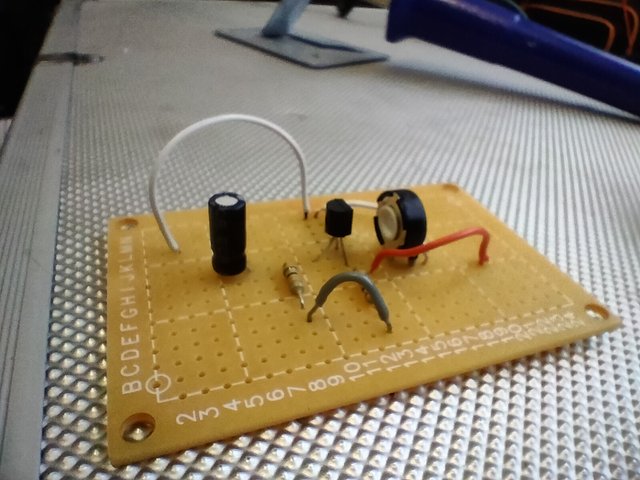
Here's the design on a stripboard:

IMG-20240409-121941.jpg


It's a BC547B general purpose amplifier, tested and working (I added flying leads to it afterwards)

EDIT : it was my first time doing a stripboard so there are some oddities like the jumper wires, it wasn't even ready at that point but it looked rad so I took a pic
 
There are some simple circuits for sine wave oscillators on the web, I will try to find one for you that you can build for les than $100-.
 
here is an audio oscillator on ebay for $75.00.
/www.ebay.com/itm/353880251850?var=0&mkevt=1&mkcid=1&mkrid=711-53200-19255-0&campid=5338590836&toolid=10044&customid=923ae698dfc41de91577808d3c188772
 
This is what you want to build fir a test oscillator. ZThe only special part is the 2 gang 10k pot; it should have a linear taper, the diodes should be 1N4148. A 5434 opamp is a good choice, it will give at least 7v p-p output.

tps://eng.libretexts.org/Bookshelves/Electrical_Engineering/Electronics/Operational_Amplifiers_and_Linear_Integrated_Circuits_-_Theory_and_Application_(Fiore)/09%3A_Oscillators_and_Frequency_Generators/9.02%3A_Op_Amp_Oscillators
You will need to add a 250uf electrolytic cap w the + connected to the output of the op amp. Then connect a 10k audio taper pot to the neg end of the cap & take the signal from the wiper of the pot. It would be best power the ic from a small ac powered bi polar supply; +- 15 vdc.
 
Last edited:
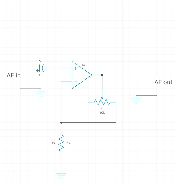
I also did a NE5534 preamp for reference :

IMG-20240412-144850.jpg


It offers less distortion, more gain and is non-inverting. Runs fine on 9VDC.

ne5534pre.jpg
 
That op-amp circuit has no path for bias current to the non-inv input, and no DC reference for the half supply point. I don't see how that could run at all from a single 9v supply.
 
I also did a NE5534 preamp for reference :


It offers less distortion, more gain and is non-inverting. Runs fine on 9VDC.

ne5534pre.jpg

Not shure sticking a pot in the feedback loop is a good idea :unsure:

That op-amp circuit has no path for bias current to the non-inv input, and no DC reference for the half supply point. I don't see how that could run at all from a single 9v supply.
yes and yes...

The op amp + input needs a dc voltage reference. For a 9V total supply the + input should be referenced to v/2 (4.5V).

Putting a pot in the NF loop can be done but wiper bounce can cause scratchy noise as gain goes high during momentary wiper disconnect from the substrate. Putting a small cap from output to minus input can damp noise from wiper bounce. A large resistor in parallel with cap across the NF can present stable high gain if pot fails open circuit (this is common design concern when using cheap trim pots.)

JR
 
?I would advise against having the pot in feedback loop. Also battery power will not be the best; rather ac powered is more stable & no worris when battery is slowly dying & it removes the limit on the output level.
 
Before turning on the soldering iron turn on the PC and download LTSpice,, a very easy to learn circuit simulator, and run your ideas thru it.
It will quickly find out what does not work, and mostly what does.
It is free, has a massive user group, and works great.
 
Well, it works.. but another problem occured.

When I switched the transistor amp to the NE5534 one the headphone volume stopped working.

I tried fixing it first by running the ground via a potentiometer (pot before opamp) but it didn't work, then I did a quick TS cable to pot with alligator clip test, it worked so I wired the pot after the headphone amp.

Could this be due to the ground signal affecting the opamp output? I read about virtual ground or something.

Anyway, thanks for the replies. I'll try to be careful but I really needed an internal gain control and I remember seeing circuits where the feedback loop controls the gain.

I already have SPICE on my Android, a book I read on semiconductors suggested using APLAC.
 
I'm afraid currently pretty much everything is out of my price range. But thanks for the sine wave generator link. So far I've been using a smartphone with Audacity.

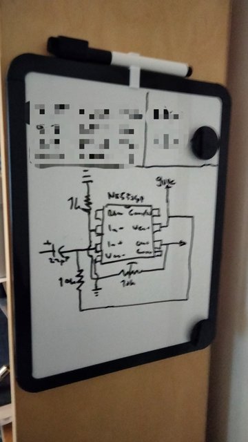
But the good new is I got the NE5534 working as a mic pre using an elecret mic.

1000002076.jpg


I also got this fancy whiteboard really cheap for planning and sketching. In my breadboard circuit I omitted the 22uF cap.

EDIT : setting the gain is VERY critical in this thing.. otherwise there'd be a loud screech. I need to poke around with the circuit before putting it on stripboard.
 
Last edited:

Latest posts

Back
Top