[FEELER] C12 Clone Project

GroupDIY Audio Forum

Help Support GroupDIY Audio Forum:

This site may earn a commission from merchant affiliate links, including eBay, Amazon, and others.

Please indicate which project configuration would most interest you.

  • pcb's only

    Votes: 28 14.1%
  • pcb's and donor microphone

    Votes: 22 11.1%
  • partial kit (pcb, electronic components, transformer)

    Votes: 37 18.6%
  • partial kit with donor microphone

    Votes: 29 14.6%
  • complete turn-key package

    Votes: 83 41.7%

  • Total voters
    199
chunger said:
HellfireStudios said:
Do you know if headbaskets will be available as a seperate item yet? I'm happy with my C12 clone as is, but a more-accurate headbasket would be nice. I might even do two, if my budget allows...

-James-

I should hear news from the factory sometime tomorrow.  There have been some developments.  I'm sure minimum order quantities will be much higher than necessary to support this specific project, so yes. . . these will be available separately for folks to retrofit their Apex 460's and other similar mics that are cut from the same tooling.

Good news. Will the headbaskets be chromed/nickel plated? (please say yes!  :D)

Dylan
 
My leaning is Polished nickel plated.  As I understand it, nickel plate finish can vary from batch to batch and all of the microphones I'm importing are bead-blasted matte nickel, so if I do the headbaskets in polished nickel, they will contrast with the matte bodies and there will not be problems with finish mis-match between batches and even between different factories for that matter as I know several factories use this tooling.
 
chunger said:
My leaning is Polished nickel plated.  As I understand it, nickel plate finish can vary from batch to batch and all of the microphones I'm importing are bead-blasted matte nickel, so if I do the headbaskets in polished nickel, they will contrast with the matte bodies and there will not be problems with finish mis-match between batches and even between different factories for that matter as I know several factories use this tooling.

Awesome! Can't wait.
 
Matador said:
Is anyone interested in teardown pics of the stock Alctron mike and PSU? 

I'm nowhere near the photo documenter that Chunger is, but if anyone is interested in seeing the guts and how things are dismantled I can try to take some pics along the way.

I've got my popcorn ready also, you guys so RULE!
Hey Matador, a big sheet of white paper may get your pics 1/2 way there?

Thnx
T
 
Exciting shipment received from the PCB house today!  These came in must faster than usual:  business must be slow in those parts.

I apologize for the crappy cell-phone pics:  I'll take better pictures when stuffing of the boards happens.

Here is the main PSU board:

c12_psu_first.jpg


Main microphone PCB:

c12_mike_pcb.jpg


Here the two microphone PCB's are set together:

c12_pcbs_both.jpg
 
What's the deal with the headbasket on this unit? Do we have an idea what the original unit is?
 
Working on the headbasket but I have run into problems with first choice factory in that they took a look at the design and don't want to build it.  I'm following up on factory 2 and 3 now but feel headbaskets may lag behind the rest of the parts.  I can get stock HT-11a headbasket manufactured with different grill material without much issue at very reasonable cost, but would much rather just get it all done at once and have the new hoop structure.
 
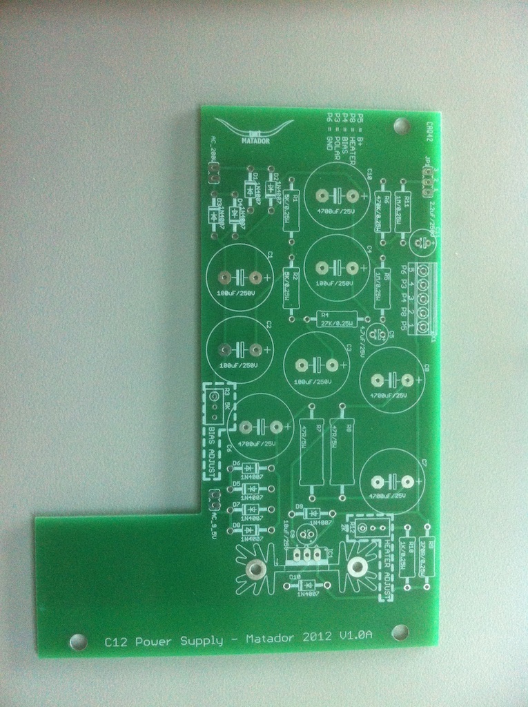
Ok here's most of the PSU build!

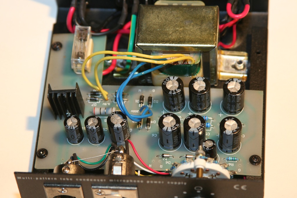
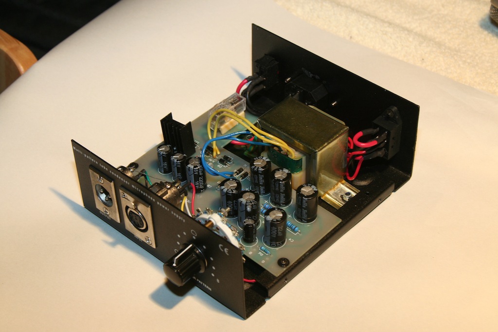
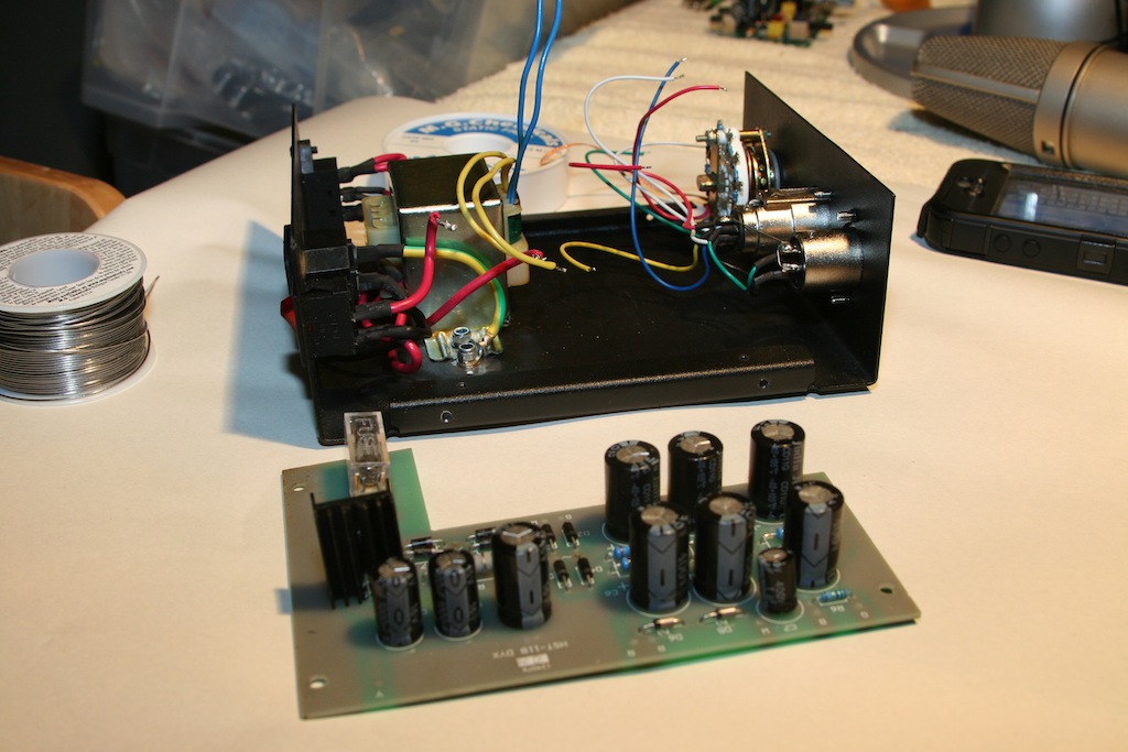
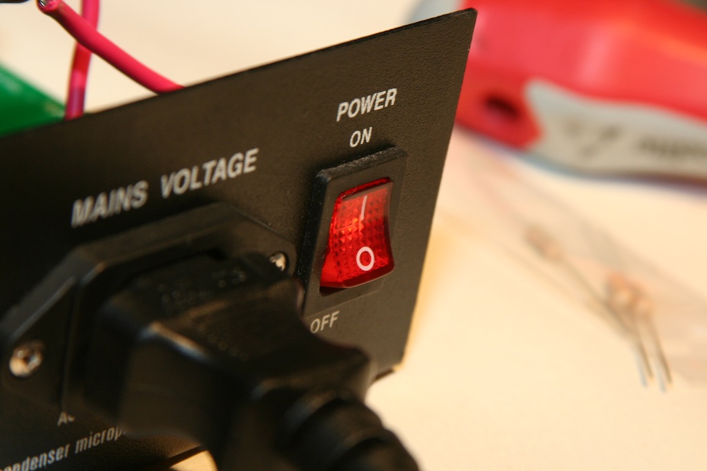
The PSU case is removed with 4 screws around the bottom sides.  Popping the lid reveals the guts:

IMG_1361.JPG


IMG_1362.JPG


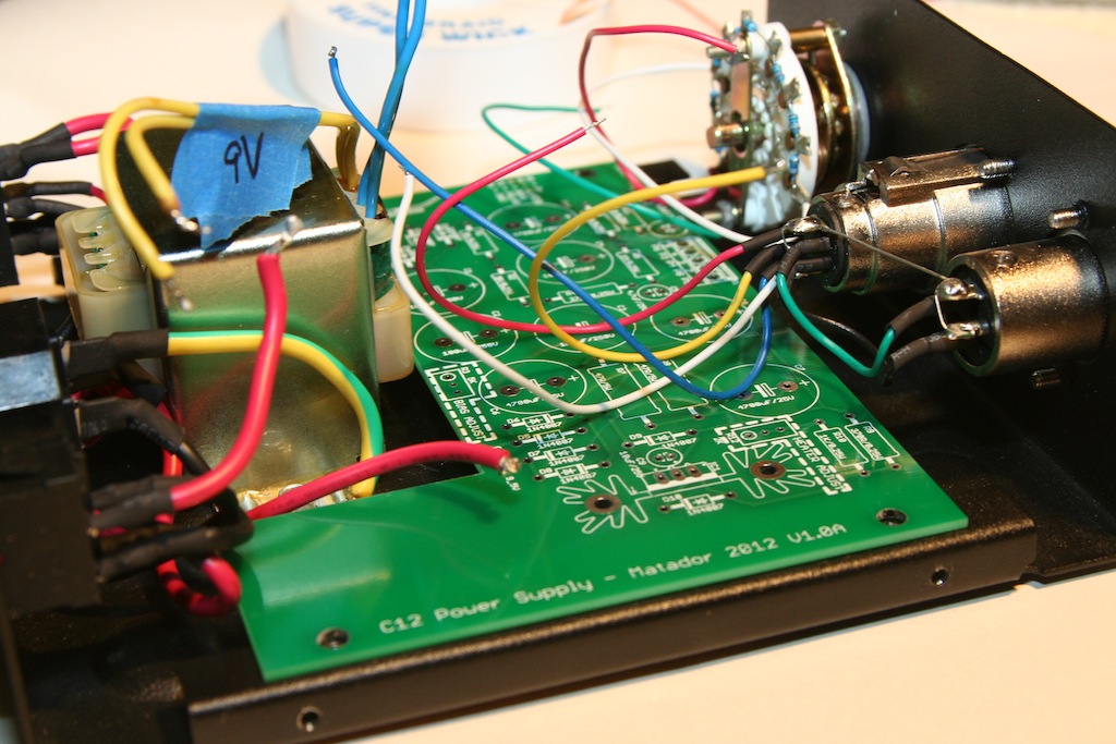
Three more screws release the main PCB and reveal the wire connections underneath:

IMG_1363.JPG


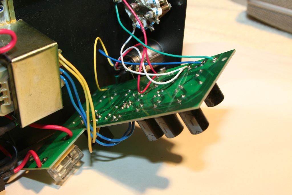
There are a series of 7 wires along the top of the PCB that must be removed:

IMG_1364.JPG


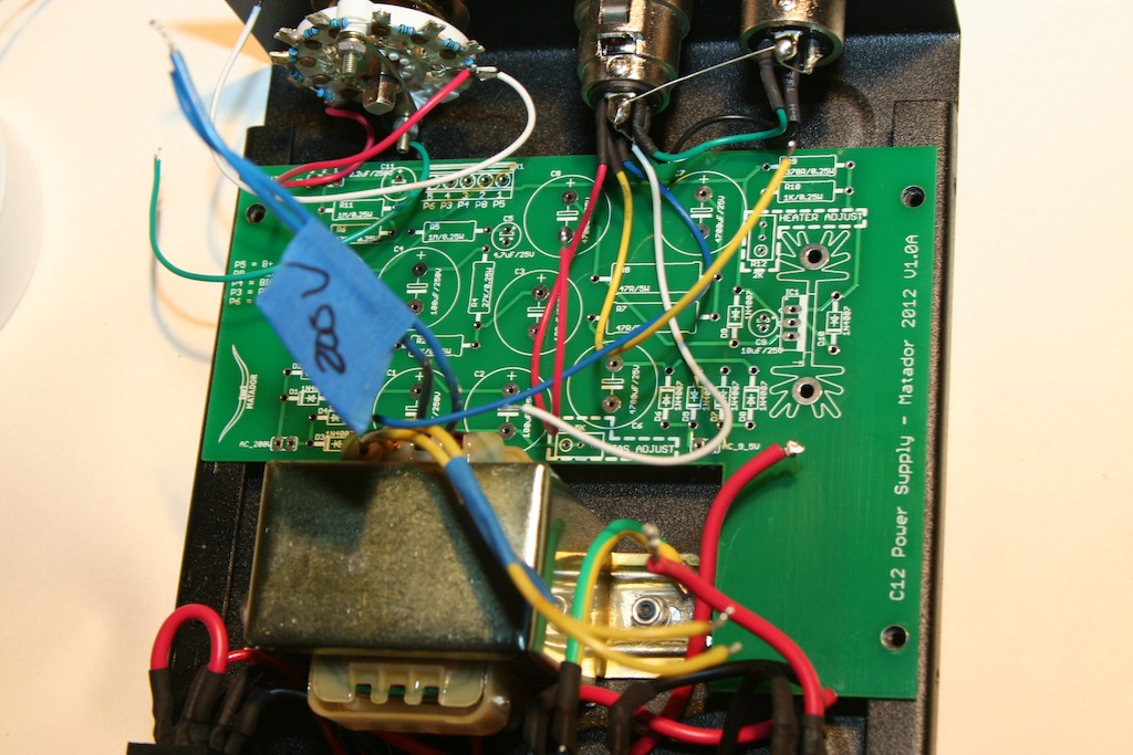
Once those are disconnected, the power transformer leads (4) must be removed.  On my unit, there were gobs of solder, so I hit it with some desoldering braid and then they pulled out:

IMG_1365.JPG


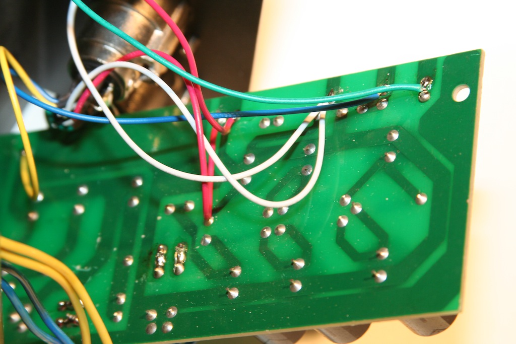
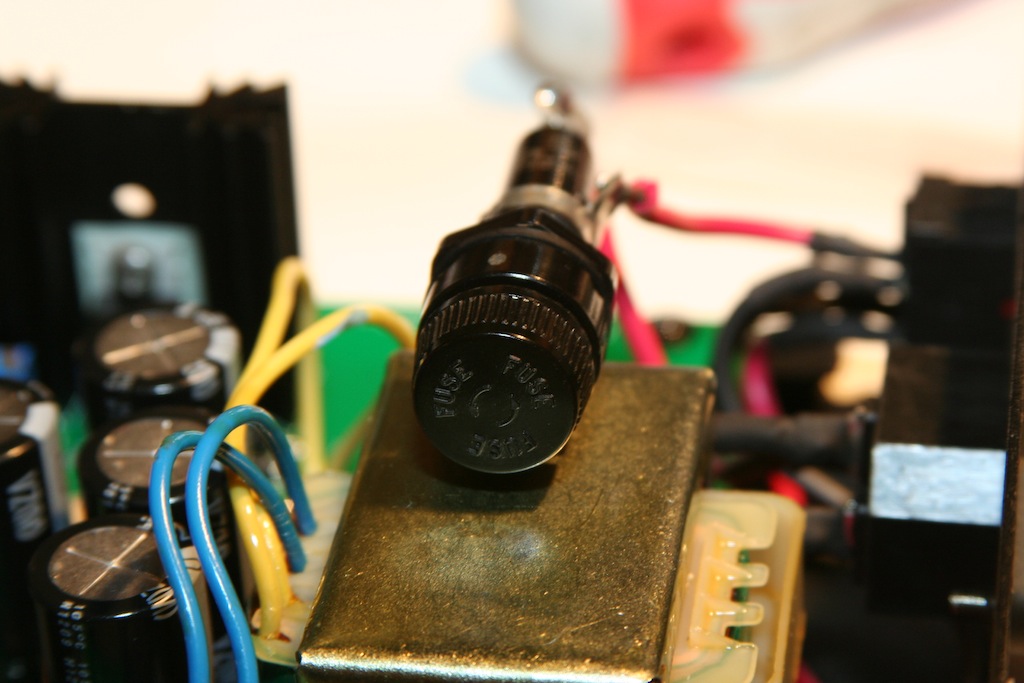
The last two wires go to the PCB mounted fuse.  Once those are removed, the PCB can be removed:

IMG_1367.JPG


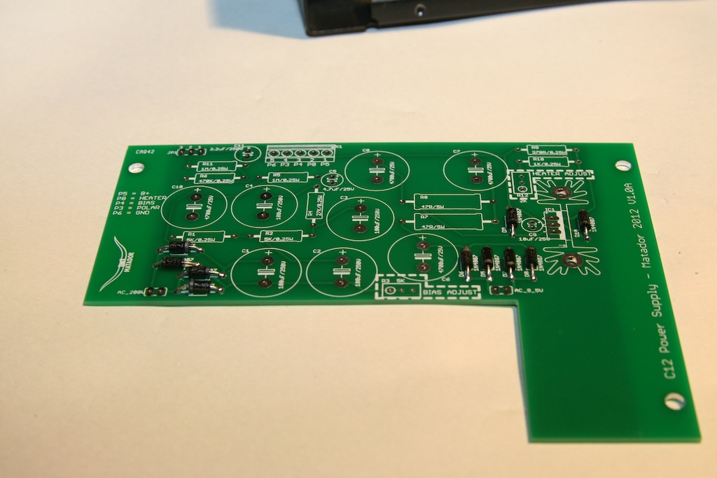
Now for the moment of truth:  test fitting the new PCB.  It looks like all of the screws line up!  Success!

IMG_1368.JPG


IMG_1369.JPG


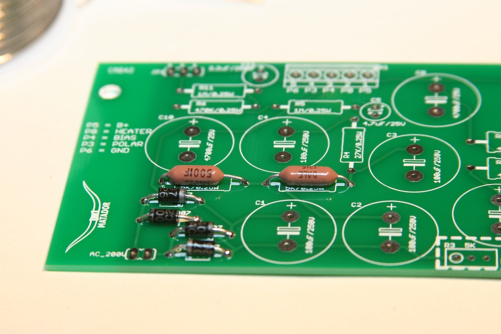
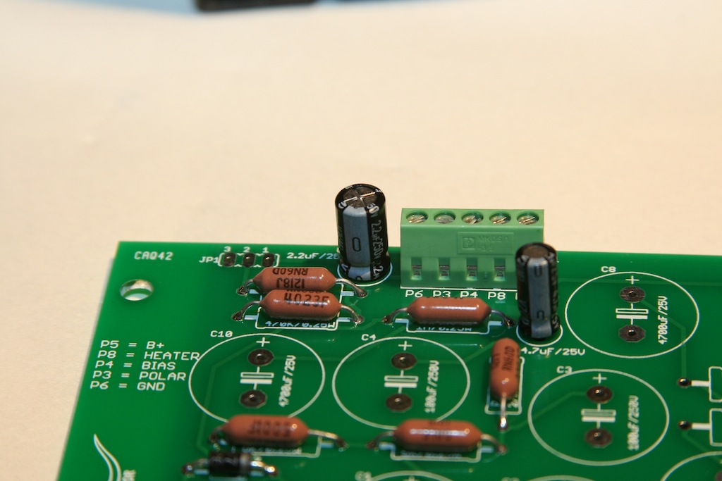
Pulling the PCB back out, I start by stuffing the 10 1N4007 rectifier and protection diodes:

IMG_1370.JPG


Then all of the 1/4W Vishay resistors:

IMG_1371.JPG


IMG_1372.JPG


IMG_1373.JPG


IMG_1374.JPG


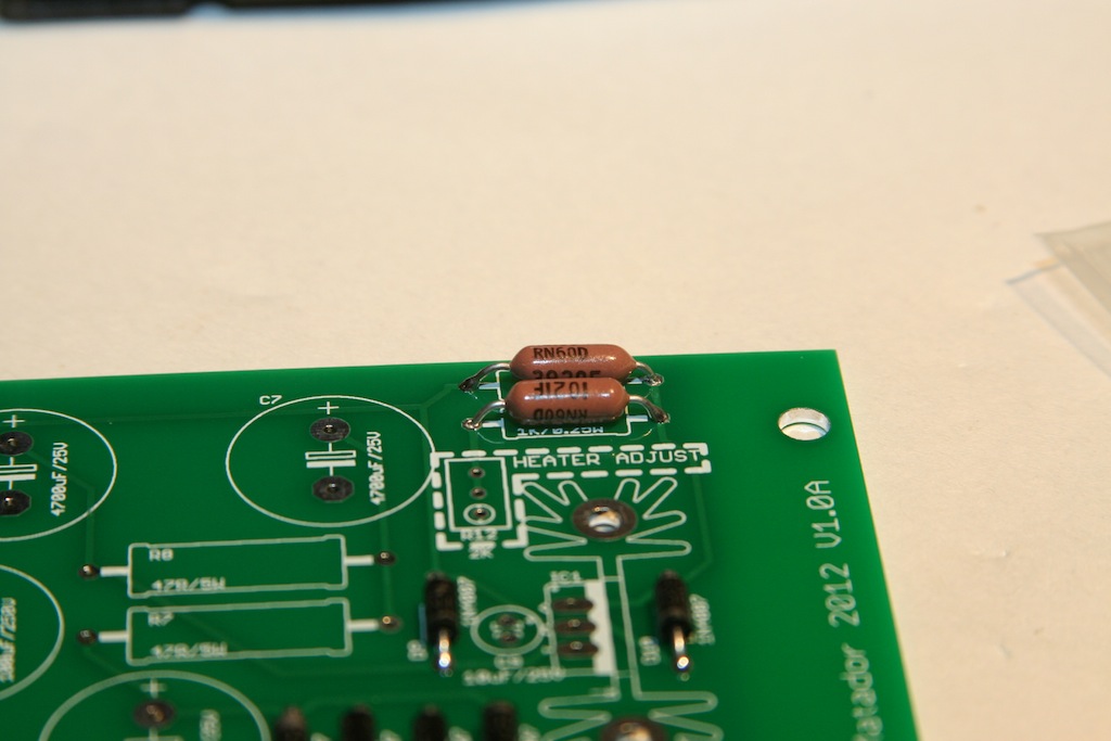
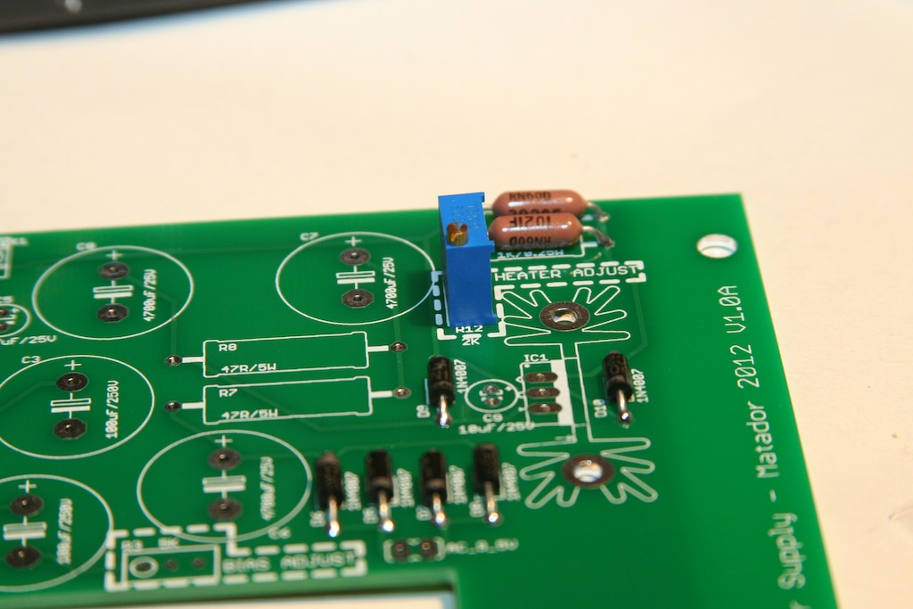
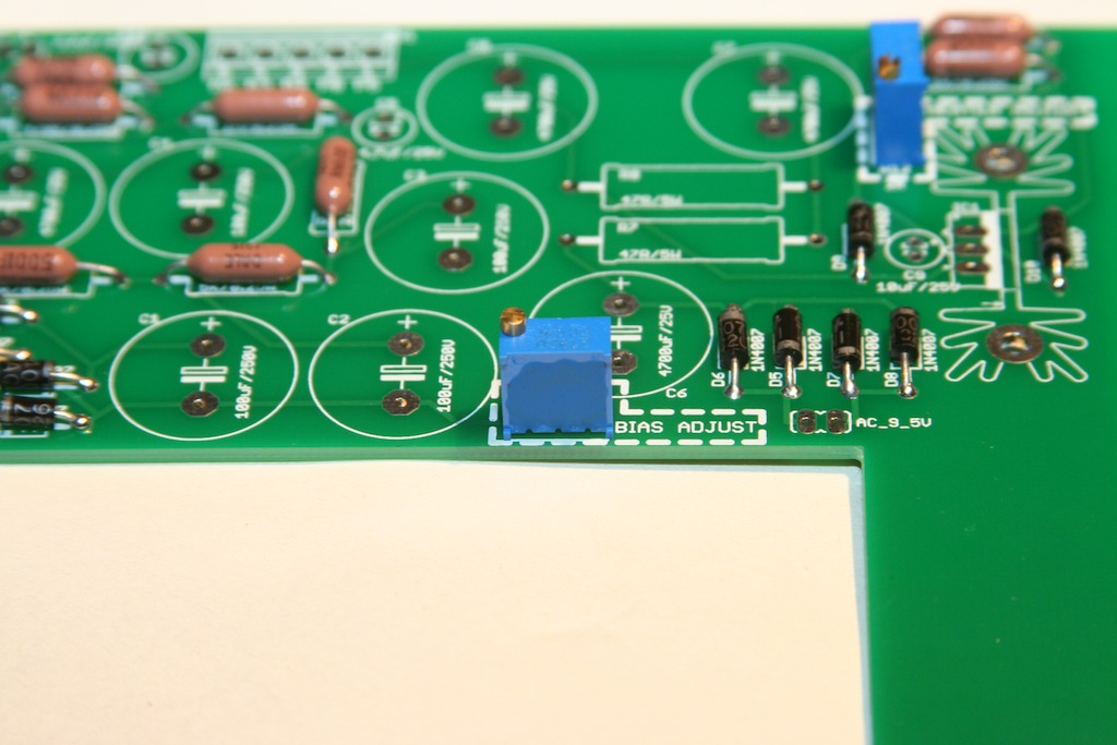
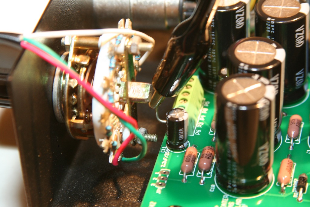
Next go the two trimmers:  one for the heather voltage, the other for the tube bias:

IMG_1375.JPG


IMG_1376.JPG


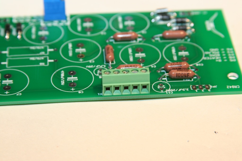
Then the screw connection terminal:

IMG_1377.JPG


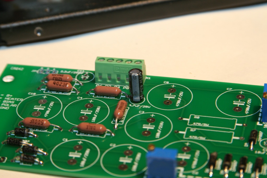
Now all of the small Nichicon caps:


IMG_1378.JPG


IMG_1379.JPG


IMG_1380.JPG


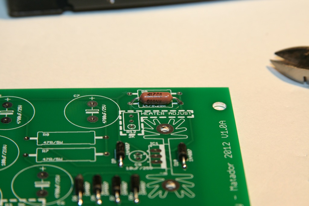
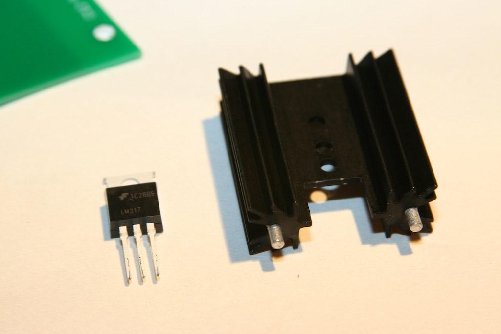
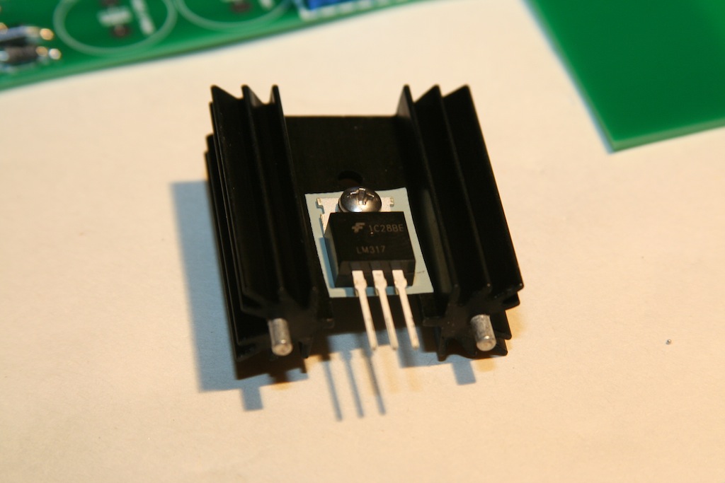
Now for the heatsink.  The LM317T regulator for the heater voltage is connected to the heatsink with a heatsink mounting kit:

IMG_1381.JPG


IMG_1382.JPG


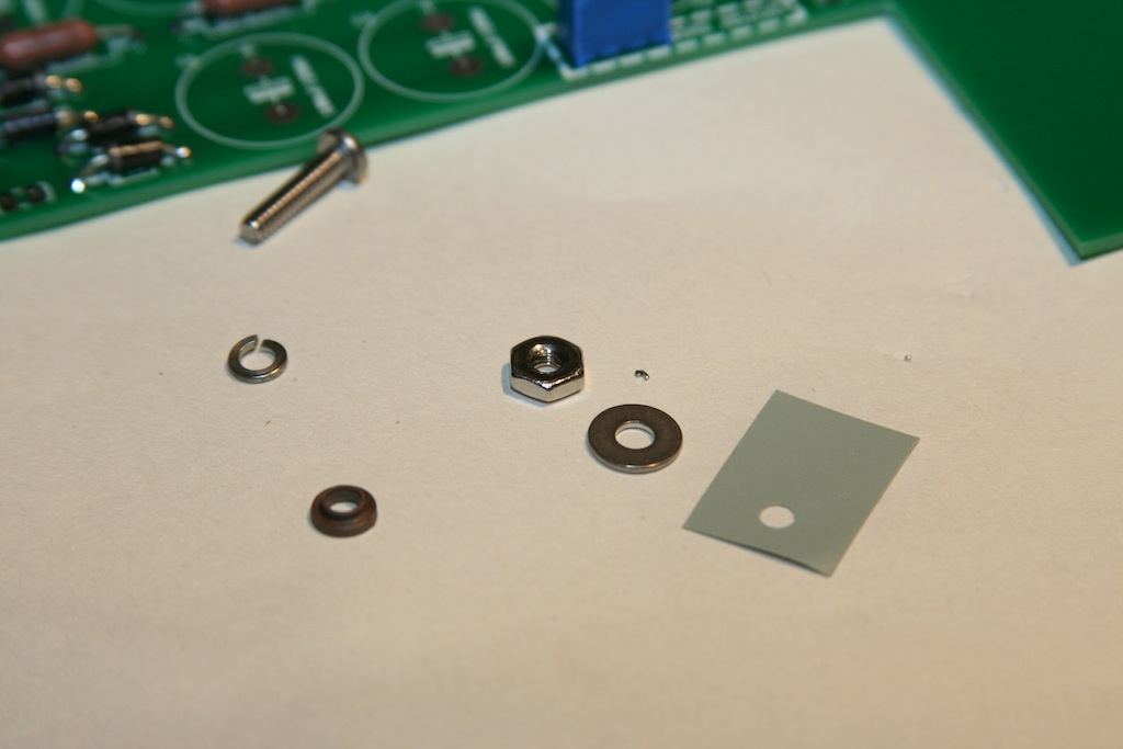
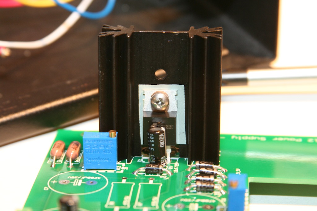
The order goes:  the bolt goes through the insulating washer, then through the LM317T, then through the insulating thermal pad, then through the heatsink.  On the other side of the bolt: a washer, then a lock washer, then the nut.  After this is loosely screwed together, the whole mess can be placed on the board.  The heatsink has two mounting tabs that get soldered to the PCB:

IMG_1383.JPG


IMG_1387.JPG


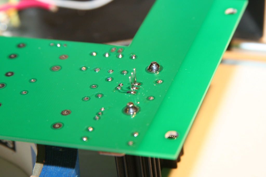
This is tricky to solder due to the high thermal mass.  You need a good iron for this!  Hold the heatsink, and tack one of the tabs and make sure everything is sitting down on the PCB.  Then you can solder the other tabs, the three LM317T connections, and then back to the first tab:

IMG_1388.JPG


Then you can tighten the bolt snugly (but not tight!).  It's just there to hole the regulator to the heatsink.  With this mounting kit, the heatsink does not rise up to the output voltage, which is much safer if you monkey around inside the case with a screwdriver.

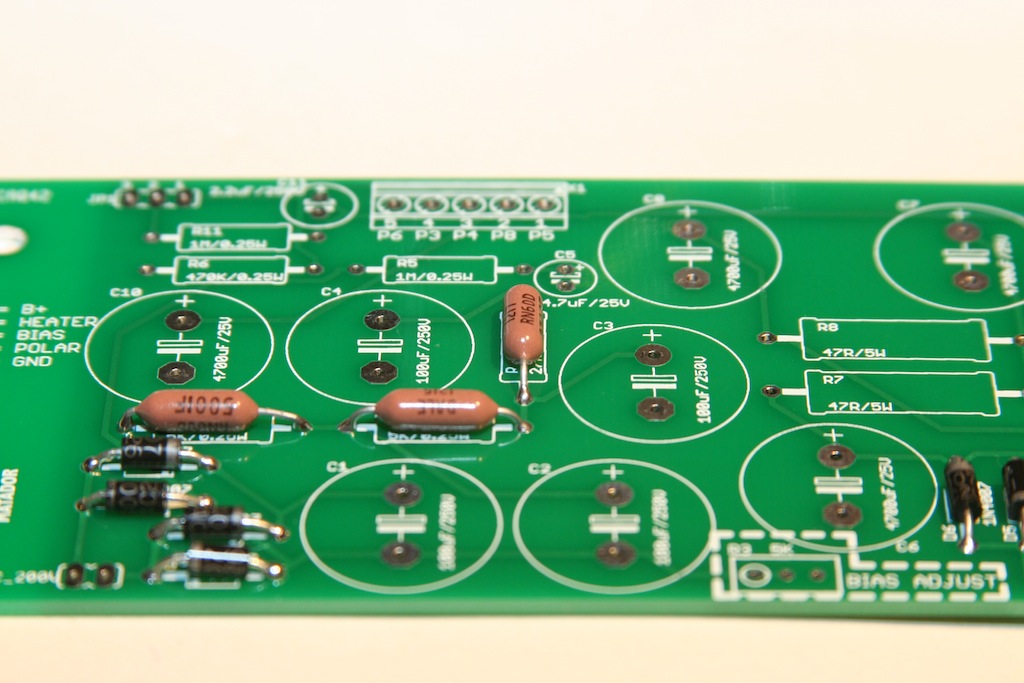
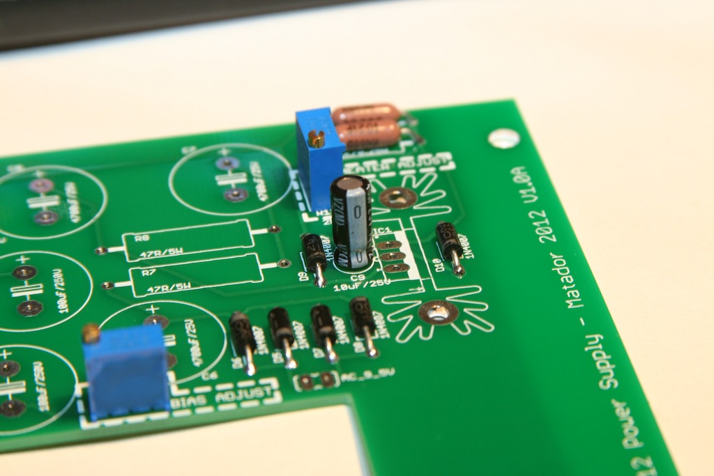
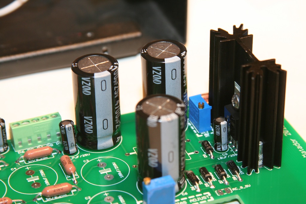
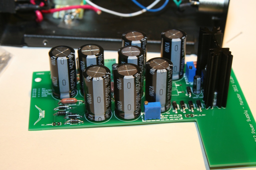
Now it's time for the large caps.  There are four 4700uF heater caps:

IMG_1389.JPG


Then the 100uF 250V caps for the tube B+ supply:

IMG_1390.JPG


There's a lot more filtering on my board as compared to the original!

IMG_1391.JPG


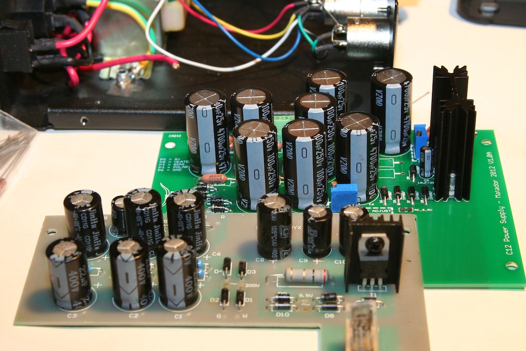
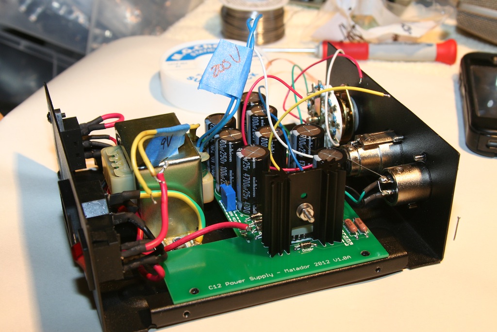
Back into the chassis to make sure everything fits and everything has clearance:

IMG_1392.JPG


Success!

Next I need to redo the polarization switch with new resistors, then install the 1W 5ohm resistors into the heater supply.

I also didn't like the PCB mounted fuse:  I'll be replacing it with a chassis mounted one so that the fuse can be replaced without taking everything apart.
 
Some more progress.

Installed some 1.8 ohm resistors into the heater RC filters that go before the regulator.  This should give roughly the correct voltage drop before the regulator.

I will tune these later:  the math says, we need roughly 2V top across the regulator.  This means that after the rectifier, there should be about 13V.  This is a 5V drop across these two resistor at 350mA of heater current.  This is about 5 ohms per resistor.

IMG_1394.JPG


Next I wire up the fuse holder (temporarily, before I drill out the chassis for it) with a 250mA fuse.  Don't want to burn down the house!

IMG_1395.JPG


I plug it in, and flick on the switch, and wait to hear that sizzling that comes right before a cap goes blam....but nothing!

IMG_1396.JPG


I rig a temporary post to the ground terminal so I can ground my meter:

IMG_1397.JPG


No-load B+ voltage was way over as expected:  the transformer should put out about 280V after full wave rectification:

IMG_1400.JPG


The heater voltage way very high:

IMG_1401.JPG


A few turns of the heater adjust pot brings it down:

IMG_1402.JPG


I installed a 100K test load on the B+ line, and a 20 ohm test load on the heater.  B+ dropped to 200V and heater stayed at 6.3V!

Success!

IMG_1407.JPG

IMG_1408.JPG


I just need to wire the polarization switch and the PSU is good to go!
 
Back
Top