Feeler: 'Easy' He69

GroupDIY Audio Forum

Help Support GroupDIY Audio Forum:

This site may earn a commission from merchant affiliate links, including eBay, Amazon, and others.

ramshackles

Well-known member
Joined
Dec 18, 2011
Messages
521
Location
Riorges, France
I'm about to finish the pcb layout for an 'Easy69'....a simplified version of Igor's He69. I'm doing it on a eurocard for my own purposes (I much prefer eurocards), but if there is any interest I can stick some gold fingers on for 51x....

The idea is to make a much simplified build, so, less configuration options, alternatives for hard-to-find parts and a more spacious PCB layout (which is easy when you remove some options).

Here is how it is:

- THAT1246 input only
- Choice of transformer outputs (the standard lundahl and Im looking at either sowter/carnhill and cinemag/jensen possibilities aswell)
- single board, bigger pads, more space
- no bypass
- carnhill inductors
- looking at including other switch possibilities aswell as grayhills.
 

Attachments

  • Easy69.pdf
    52 KB · Views: 349
Sounds awesome, I'd definately be keen to build a stereo version of this eq. How's it sounding so for ? I'd imagine 2 channels would fit nicely in a 1RU case
Cheers
James
 
I notice you schematic does not have the EQ in/out of the original. This is very handy for comparing the effect of EQ and is quite simple to implement. I also notice you have Kicad schematic symbols for 12 way switches. Are they ones you created yourself?

Cheers

Ian
 
Yes, I took it out to get 'simplest possible' version, but I you are right and I should put it back in. Igor's version had a more complicated implementation with a couple of relays; this also seemed to be the area that didnt work well for a lot of people (for whatever reason) so Ill do a simpler version.

I think I found those symbols on the net, but they should be available on my google drive folder:

https://drive.google.com/folderview?id=0B6LqEShkjOdRR1dyMjVGY2l4ajg&usp=drive_web
 
frazzman said:
For a simple bypass maybe use a simple dpdt switch to switch input xlr to output ?

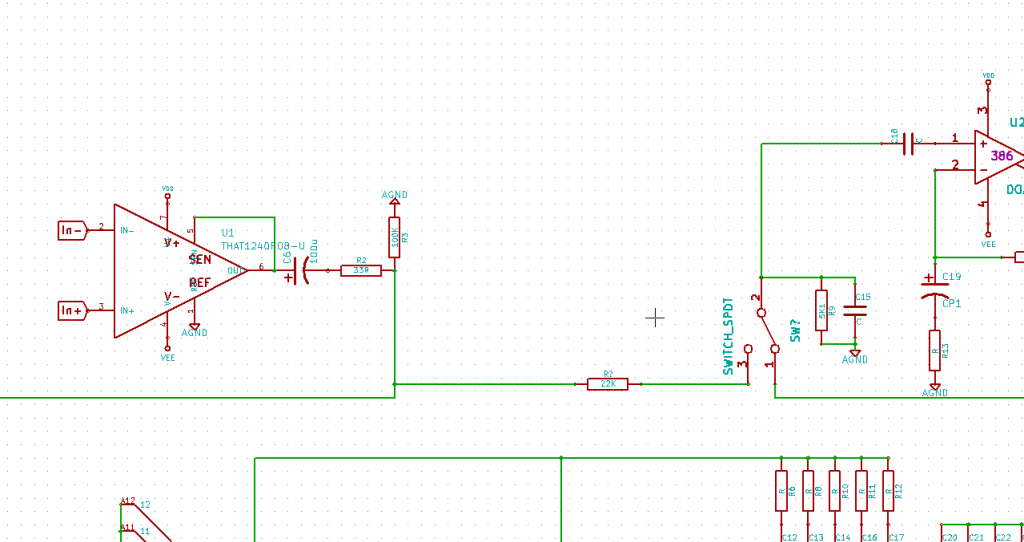
The original uses a simple SPDT. The reason it can do this is that the EQ basically consists of a pot divider consisting of the 22K pot used for mid boost/cut and a 5.1K to ground. To bypass the EQ you just switch the 5.1K from the pot to a 22K connect to the input.

Cheers

Ian
 
Sounds good; SPDT. I'll fill that in tonight. Just noticed that I haven't filled in most of the part values on the schematic, so I'll correct that too.

For the output transformers, I'm thinking Lundahl 1517, sowter 5069 and one other option?
 
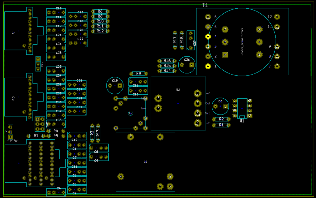
Im having a rejig of the layout, here is the placement so far:


I think it might be possible to mount the switches on the board aswell, so there is just the pots to wire up
 
I notice the bottom switch is a 3 deck type. For the Helios you only really need a 2 deck one. Also, there are some quite large value caps in the bass boost and cut circuit so you might want to check spacings between them.

Cheers

Ian
 
ruffrecords said:
I notice the bottom switch is a 3 deck type. For the Helios you only really need a 2 deck one. Also, there are some quite large value caps in the bass boost and cut circuit so you might want to check spacings between them.

Cheers

Ian

3 decks because audio maintenance doesn't stock 2 decks; the 3rd deck is not used, so should also be compatible with the 2 deck switches. It's really just to make parts sourcing easy (and so I dont have to remove decks of switches or anything).

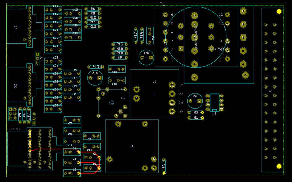
You're right; the biggest capacitor is 680nF, which can be about 7.5mm diameter for the wima's so more generous spacing is needed there...
 
I don't think there is enough space to mount the switches on the PCB comfortably :(. I wonder if there would be room to mount a little PCB flush to the front plate for the switches, so it can just connect to the board via a couple of headers...I doubt it though.

I increased spacing and added the Edcor footprint. There is probably even room for a 4th transformer option; I'll see for cinemag/jensen.


The KiCAD edcor footprint and the capacitor foot print is now on my drive:
https://drive.google.com/folderview?id=0B6LqEShkjOdRR1dyMjVGY2l4ajg&usp=drive_web
 
ruffrecords said:
Just a small point. I notice you do not have the usual fixing holes at the front of the PCB.

Cheers

Ian

Ahh yes, totally forgot, thanks!

I would make a KiCAD module with the fixing holes and edge connector built in, but then KiCAD refuse to treat the card edges as 'pcb edges' but rather as 'module edges', which total messes things up when you want to draw a selection rectangle and only select modules (not card edges)... anyway!
 
ramshackles said:
I'll see for cinemag/jensen.
If you have room for another one I think cinemag has a really great sound. I thought Edcor would be a good option for budget minded builders, but I for one like what cinemag does to the sound. Not to mention David is one hell of a great guy.
 
It looks like some Jensen transformers have the same footprint as the Edcor transformer...haven't checked thoroughly, but that could be quite a happy solution:
http://www.jensen-transformers.com/datashts/11dmpc.pdf

If it matches I will leave it at that for now. Will come back to a cinemag possibility when the rest of the board is done.
 
ramshackles said:
Bypass switch...

That is basically it. I think the original uses 24 or 27K, I forget which. It might need to be select on test (SOT) because the end to end value of the pot is probably only 20% tolerance.

Cheers

Ian
 

Latest posts

Back
Top