LA2A - rather poor specs. Any DIYers tried to improve it?

GroupDIY Audio Forum

Help Support GroupDIY Audio Forum:

This site may earn a commission from merchant affiliate links, including eBay, Amazon, and others.

David Kulka

Well-known member
Joined
Dec 10, 2006
Messages
242
Location
Burbank, California
With all due respect to the venerable and wonderfully musical LA2A, whose manufacturer I have had a decades long relationship with, I must say that it has some pretty unimpressive specs. To wit:

Maximum output level of +16 db; headroom of only 12 db over the +4 nominal output level. Perhaps lower than any other piece of pro audio gear in common use. In a modern recording environment you need to hit an LA2A VERY gently, or it WILL distort.

Noise level is specified as 75 db below +10 dbm, which equals 69 db below +4 nominal output level. That's pretty noisy. Typically, most of this noise is hum. If you set an LA2A next to a Pultec EQ and compare background noise, the LA2A won't even come close.

I agree with UA's philosophical direction to build re-issue units exactly like the originals. I would not be willing to modify an LA2A for a customer because it would just be wrong. But you DIYers who build them from scratch, have any of you tried to make improvements?

Shooting from the hip, and daydreaming with little technical research to back me up, here are some things I might do if I wanted to build a "better" LA2A:

1. Use an output transformer with a higher primary:secondary ratio, to boost the output level (and headroom) by 4-8 db.

2. Reduce overall gain by the same amount, to compensate for the increased noise level caused by the above change.

3. Find ways to reduce the inherant self-noise of the LA2A. I would concentrate on reducing hum by cleaning up the power supply rails, improving the internal wiring, and perhaps using DC on the tube heaters.

If successful, the result would be an LA2A having less noise and more headroom, with no compromise to the classic dynamics and tone.

I'm not saying that any of this would be easy or even possible, but the homework might be time well spent. Again, I feel obliged to state that I go way back with the URC and UREI, service vintage LA2A's for many clients, and think they sound just amazing just as they are.

Anybody?
 
Well...Joe made this thing called the VOC2... :grin:

VOC2%20800.jpg


Actually I think improving the noise and headroom is the easy part and it really does make the concept better and more versatile, in my experience anyway.

The hard part is finding something to replace the T4b that sounds and behaves the same but isnt such a pain in the arse to make. We hand make our own version but its very labour instensive and no two are ever exactly the same. Close but not identical.

So yes, great idea, but the GR element is the thing to focus on IMO.


M@
 
Instead of using a higher-ratio output transformer, I'd re-work the values in the White cathode follower output circuit. It's running pretty "cold" as it is. In one of my line amp* designs, I've gotten +27dBM (at onset of clipping) into 600 ohms using a 12BH7 White cathode follower biased for 15mA or so plate current, driving a 2:1 output xfmr. Driving a higher-ratio (say 4:1) xfmr, it wouldn't even break a sweat, so to speak.

jensen transformer published a ready-made mod for the output section that accomplishes more or less the same thing I'm talking about.

http://www.jensen-transformers.com/as/as091.pdf

I'd definitely use a lower-ratio input transformer.

(* Revisions to that line amp schematic, for anyone interested: add 1M from V1A grid to ground, and the grid stoppers on V2 probably don't need to be so high--try 220 ohms).
 
I seem to remember CJ had some posts about circuit changes.
 
CJ had a bunch of mods including an all octal version. :grin: What he recommended on the "standard" was to replace the plate resistors on V1 (R9 and R13) with 100k to bias those stages for symmetrical clipping and a bit less gain. Then replace the 12AX7 on V1 with a nice NOS 12AY7. Now you've tamed the gain, cleaned up the distortion a bit, and with a lower ratio input transformer you should hear some improvement. I have yet to try this on my Bloo...YMMV.

A P
 
Matt, interesting reply, though it sounds like we may be on opposite sides of this discussion.

You comments seem to suggest that the T4B is the weak link here. I would say that the T4B is the beauty of the LA2A, and is the component most responsible for what we like about the LA2A. As mentioned in my original post, I think that noise and lack of headroom are the weak areas, neither of which are really caused by the T4B.

But maybe I misunderstood your comments. Care to explain in a little more detail?
 
I recently built a Drip LA2A. I have never used the original tho. But hum is nonexistent as far as I can tell. (Working within the levels allowed by my 002r) Even using my "bass enhanced" audio technica headphones. Actually I was expecting a little hum and noise from reading the la2a thread. ALL of it lol. But so far it is very clean. And I hit it as hard as I can with an Eisen api clone before the preamp distorts. Also used a solo 610 at high gain to get the tubes working...

This device is really at it's best at vocals and bass guitar. Last time I checked the frequency response necessary to reproduce these 2 items is WELL within the limits of it. And overkill to a great extent. However I have not used an original P2P version.

It is also possible the Drip PCB version has better specs. But I have not measured it or have the ability to. But for what I am using it for I am completely satisfied.

John
 
[quote author="David Kulka"]Matt, interesting reply, though it sounds like we may be on opposite sides of this discussion.

You comments seem to suggest that the T4B is the weak link here. I would say that the T4B is the beauty of the LA2A, and is the component most responsible for what we like about the LA2A. As mentioned in my original post, I think that noise and lack of headroom are the weak areas, neither of which are really caused by the T4B.

But maybe I misunderstood your comments. Care to explain in a little more detail?[/quote]


Hey David,

No no I love what the T4b does, its THAT sound were all so familiar with. The problem is making them and matching them. There are a number of characteristics of each LDR that have to be matched and getting a pair that are exactly the same is rare. Making many units that are all the same is just about impossible.

So thats what I mean about the problem with the LA2a being the T4b. If someone could come up with a replacment for it that still did the same job and sounded the same but was easy and cheap to duplicate precisely, then youd have something. Improving the audio circuitry is pretty straight forward in comparrison.

If however youre just building a one off unit for youself, this isnt really a concern. As long as you dont mind spending the dough on a T4b. :wink:


M@
 
David has a depot full of original JBL T4Bs in his stock, dude. The guy is an ex-UREI serviceman, his family won't need no DIY T4Bs for at least another three generations I can guarantee ya :cool:

If you happened to have bought any original T4Bs from Ebay, chances are that you bought them from him :green:

Mach
 
What Mach wrote is basically true and I wasn't quite sure how to respond to the T4B consistancy issue, since there seemed to be a slight conflict of interest.

Some knowledgeable people have commented that there is more variation between NOS T4B's than we would like, and this may be true. I admit that I've never done any meaningful tests. The main reasons are that the T4B's I stock are in sealed boxes and I'm not too thrilled about opening them up, and that useful comparson tests could be very time consuming.

I do know that in cases where I've replaced both T4B's in a pair of racked LA3A's, they tracked and matched well without having to select "matched" T4B's, etc. Some luck may have been involved in these cases, but this has left me with the impression that variation between individual units is not really a big issue. If others here disagree I'd be interested in hearing their views and discussing this, though.

Slightly off topic, I will mention that in old used T4B's we have seen really odd problems with frequency response and in some cases distortion. It seems very strange that an bad T4B would develop this symptom, but for some reason, they can and do.

Back to the original topic, I really think that the biggest weaknesses with LA2A's (both manufactured and DIY) and the limited headroom, and somewhat high noise spec. Talking about unit to unit variation - the 12AX7 input tube can have a huge influence on noise and hum. If I were building an LA2A from scratch, this is something I would really watch.
 
aside from a 'marketing' point of view , wich is not the case.

i build t4s now and again , but the common fact is ive bought
scored of urei t4s and ua t4s just to dissmantle them and test
their integrity in order for me to have a more accurate
product.

it seems like with the urei , some are good and some
are bad.

meaning some are the traditional speed recovery time
and some end up being quick to recover negating that 'LA' feel .

NOS t4bs are un matched and do differ in specs from t4 to t4.

this is a fact and is real.

as for distortion coming from the t4b , that is not so likely.
it's just a resistor , thats it. a bad photo cell perhaps ,
but it does sound strange that this distortion would be coming from such a
simple part of the equation.
but does bring up the idea that the capacitor could be on it's
way out , but that would just deal with the light panel working or not.
distortion could mean a crapping photo cell.

but the problem would point more towards the othe cicuitry out side
of the t4s arena.


one might prefer to have a UA t4 over a urei NOS in a heart beat.
simply the screening processs is more up to date then on the urei's.
and the performance is accurate and consistant.
yet i find that theres nothing like the real thing sometimes.

the weak link in the t4 design can be noticed when one looks at the circuit
board , the cap power is very close to the 'signal' traces etc.

it's actually a crappy layout , but it has lasted the test of time i guess.

there can be some real improvements in the design and layout of a new t4b.

g.
 
Some observations about having built, repaired, upgraded and "skunkwors-ed" a few T4's over the last few years:

UREI (and Teletronix) T4s ARE matched unit-to-unit. Not to within 1% or anything (that would almost certainly mean a rejection rate in excess of nine out of every ten opto-resistors purchased: They do vary a LOT in same-batch production).

However, the LA-2a, LA-3a, BL40 and anything else that uses a T4 are all set up in feed-BACK limiting, which means that they do self-correct.

Onset of limiting (threshold) is largely set by the turn-on voltage of the EL panel, and this is a number which DEFINATELY creeps up with use.

If you compare a well-used T4 and a virgin one, the 'tired' panel will have a higher turn-on threshold, and a dimmer output-per-volt above that. A slightly relaxed compression curve is the net result.

okay, LOTS of people have built their own T4s WITHOUT matching the cells, and they'll notice that the GR diaplay and actual signal reduction doesn't track very well. Many don't even adjust R25 (I ALWAYS do!) to correct much of this, (Put a trimpot in there with croc-clip leads, adjust as you would the 1176, then when it's best matched, replace it with a fixed-value resistor of whatever value it turns out to be). They then assume that T4 optos don't track very well.

JBL/UREI used to include a pre-tested resistor for R25 in the white cardboard box with your T4. -I'm sure that David's have them. -They were most commonly taped to the T4 can, so they didn't get seperated. Lots of people didn't use them when they swapped T4's, they just either tossed them away, or added them to their resistor collection.

Now, Given that the LA-2a is in itself self-correcting (feed-back), and that the GR display CAN be matched for usable accuracy, Two LA-2a's will both compress at right about the same amount, threshold and ratio, given equal 'aging' of the T4s.

Here's the difference, given their 'Self-correcting' nature, they may be using DIFFERENT AC control voltages for the same given signal gain reduction. -understanding that, there is a trimpot on the rear panel, which allows you to dial-down the unit which is producing more sidechain voltage signal. This DOES allow T4s to be brought eye-to-eye with each other. Any differences in curve should be comparatively small, and not truly significant.

In these days where we all have digital watches accurate to a fraction of a second per day, where VCAs can give you stereo tracking within hundredths of a dB, we may think of these numbers as dreadful, but they were used on VAST numbers of the records which we loved. -Hell, the Mastering Lab (Doug Sax) had a modified pair of LA-2a's through which were passed some of the greatest-sounding pop/rock recordings in history. (The ML mods started with transformerless in & out... transformers were de rigeur in broadcast installations, and only a fool would try a 'catalogue' installation without them, but the Mastering Lab was set up with short runs between KNOWN equipment interfaces, and this allowed them to extend frequency response and improve phase response and transient performance to an unheard-of degree.)

So here's the deal: T4 optos were selected primarily for CURVE similarity. any large deviations or sudden 'kinks' in linearity are things you can't trim out with a single tripmpot, so they are the ones which were rejected. -You can't -as I said earlier- make the optos "match" in the way you might first think, without first buying a hundred, and even then you'd be lucky to find two with acceptably constant, matching curves.

You CANNOT buy up used T4s and compare them side-by-side in the same unit as a valid test. The GR tracking (R25) HAS to be adjusted, the rear panel limiter 'response' has to be adjusted (the LF -to-HF performance of differently-aged T4s also alters) and the stereo matching control (which -from memory, I seem to recall may actually be a potentiometer which turns down the limiter's OWN feedback control voltage, making it send MORE to the stereo link in order to achieve the same GR signal... hence matching it to the other... I'd have to review the schematic)

-But basically, to summarise it and say:
NOS t4bs are un matched and do differ in specs from t4 to t4.
...is to over-simplify it to the point where people may take a surface-skim read of your testing results and assume -VERY WRONGLY- that no matching was done in the T4s. -Also, buying up used T4s, they hardly EVER come with the matching R25 with which they were supplied: that means that you have to re-perform the R25 tracking test, or the test is VERY unfair.

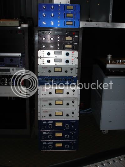
I've got LOTS of LA-2a's here... here's an example of Scenaria and I went on a mad LA2a-racking spree:
1176la2.jpg

and I've stereo-linked MANY different combinations of them, and track-adjusted them QUITE satisfactorily, even using differently-aged T4s. I've also built my own T4s with various things: experimented with LED lightsources, -even nightlight optos- and I've definately found combinations -even using pairs of NSL and pairs of clairex- which don't trim-up to satisfactory matching.

(New line for this important summary)
However, ALL of the genuine T4B's were adequately matched, with the exception of one which had been repaired by a technician who had graciously put a dated sticker on it to that effect. the different solder ages inside showed that most likely only one opto had been replaced.

I know this is a long read, but I do feel that before any statements are posted to the effect that there's no benefit (matching) to purchasing a NOS one, the statements should be tested FULLY for accuracy... Dripelectronics' experience does NOT tally with my own, and I do believe that David is not in a position to 'defend' himself without appearing to be 'pimping' a heavy investment which he made.

So I'll summarise by saying that I believe that Dripelectronics testing ethodology may be in error or perhaps has been very unlucky, because his results do NOT match my own.

Here's (briefly) how I measured the curves:

An excel spreadsheet with two lines line for each T4b under test.

A Neutrik A2 set to 1kHz, plugged into one channel of a Crown CE1000 amplifier, set to maximum gain, (at 0.7V-for-max-output rear switch setting). The output of the crown is wired to an octal-relay base, feeding the two EL panel conections. Two Fluke 87 MkIII's wired across the two pairs of opto terminals.

Plug in the first T4 after its been 'dark' for a day or two. Start with the Neutrik output muted. Sweep the output level starting from quiet-to-loud outputs in 1dB increments and note the two opto readings. Note the dB position at which the optos start to 'wake-up' (the threshold) and take a settled resistance reading for each opto, at every dB above that.

Enter the data into excel.

Plot a graph with the values. Look for kinks.

Do this over and over again, and check your measurements by throwing in a curveball, like a T4 which was home-made WITHOUT any matching, just random opto-cell selection.

Oh, and one point of David's; yes, T4Bs can and DO sometimes cause distortion. unplugging the T4 makes the distortion go away. I've seen it on several T4s, both home-made and NOS. Figures in the 1% reaion are not uncommon. -I talked to the engineer at the Mastering Lab who did the modifications to their units about my findings, and he said they had seen it too.

-Here's the odd thing though: you can make the distortion go away for a while: If you turn the GR completely off, measure the distortion at 1kHz 0VU unity gain, no GR for example. Then "blast" it with a +20dB burst increase for 3-4 seconds, and then switch back to the original 0VU test signal level. -You should notice that the distortion is now in the 0.1-to-0.2% range, but slowly creeps back up.

Again, speaking to the ML engineer, he said that they selected T4s, and that they too had noticed that the performance could be improved by what he called "washing" the optos with high level signal. (He called it "washing", I called it "Burning"... but it becams clear to both of us that we were referring to the same behaviour characteristic.)

Food for thought. -And something which other LAB users with LA2a's and access to a distortion analyser may be able to corroborate. -Not all T4s do it: about 10-15% in my experience. -With most, I was able to swap the GR and signal optos and find a less-distorted opto in the signal position. Again, because of the curve-matching, I they would still match, though R25 always had to be re-adjusted.

but does bring up the idea that the capacitor could be on it's way out , but that would just deal with the light panel working or not.
Absolutely ruled out: It does it with no gain reduction... Hopefully David canl corroborate that he's seen the same thing as I'm talking about.

Keith
 
David, I wonder if you've considered what the Mastering Lab did to theirs... I'm not sure how much of it is public domain, so I can't go into any detail really, but you're in that part of the world, and fairly 'known' as it were...

It's no secret that they were "modified" and performed VERY much better than stock units. It's also known that they were transformerless. For more info, you'd prtobably have to get some permission from the Sax brothers...

Of all the technical stuff that was done at the Mastering Labs, I don't hear of people making any "audiophile" or "Emperor's new clothes" accusations: On the contrary, most people speak about them with GREAT reverence: -The Tannoy crossover mods are just one example which springs to mind.

Keith
 
Thanks for the interesting comments. This is good stuff.

Gregory wrote "the weak link in the t4 design can be noticed when one looks at the circuit board , the cap power is very close to the 'signal' traces etc.". Assuming that he meant "weak link in the LA2A design", I somewhat agree. Much of the noise in the LA2A is hum, which probably could be avoided by changes in layout. I wouldn't call it crappy, but I do think there's room for improvement in a DIY model. (Along those lines it's worth mentioning that there's plenty of room for degradation, as well. DIY'ers should be careful about reinventing the wiring harness and layout. As with all tube gear it's very easy to create problems with oscillation, hum, RF, etc. by routing a wire differently or changing the way that some grounds are daisy chained. At some point many of us learned the hard way that the schematic and the circuit are two different things. Every wire is a resistor, and every pair of wires is a capacitor, none of which appear on the schematic...)

Regarding uniformity among new T4B's, I repeat that when we've replaced them in 2 LA3A's, the two units have always tracked closely. Keith makes a good point about bench testing of T4B's vs. in-circuit performance. The light panel being driven by the output of the GR circuit and release time set by an external capacitor mitigates most (not all!) variation among T4B's.

I know for sure that stringent tests were done when runs of T4B's were produced; I also know that JBL tracked them as they aged and saw that there was little or no shelf life problem. Also -- this really amazes me -- of the 300 or so T4B's we've sold and installed in the past few years, I haven't encountered even one bad unit. I hope that doesn't sound like 'pimping' (thanks Keith for the supportive comments) but it's true.

Yes, NOS T4B'S include a replacement R25, but these resistors are not selected for each unit. They're all the same value and are only there in case you are replacing a T4A, which used a different value. These days we hardly ever see T4A's -- maybe 5 or 10% of LA2A's will have one, and they are almost always bad. Keith, that's an excellent idea though - to select R25. I'm going to try that, and it may become a standard part of our service routine.

On LA2A's and LA3A's you can zero the meter in GR mode, but you can't zero it in output mode. Most older VU meters will read a little low, so "Zero VU" ends up being about +4.25 or +4.5. The one and only mod that we do on these models is to replace the fixed resistor in this circuit with a new fixed resistor and trimmer, so that the meter can indicate Zero at exactly +4 out. (And don't forget, for best square wave response these models need a termination resistor on the output!)

Regarding the distortion issue with old (faulty)T4B's. Without question, we have seen this issue in our shop. We service plenty of LA2A's and LA3A's and each unit gets a distortion check with the Audio Precision at least once, often 2 or 3 times. It's like Keith said -- we'll see some funny distortion, pull the T4B, it goes away. Plug in a new one, everything's fine. We've never seen distortion on a new one -- just old ones. It was a little surprising at first, but we seen distortion caused by faulty capacitors, and even resistors, so why not a photocell. My guess is that degradation in the cell results in a slight diode action; the positive or negative half of the waveform goes a bit sour. It's definitely something inside the can, not a capacitor. I'd be surprised if the problem was caused by the EL panel; I wouldn't think the long time constant of the lamp-cell combination would "pass" harmonic distortion in the audio range. At the moment I'm in the back seat of a car on the German Autobahn but I think we saved a distorted-output T4B as a curiosity -- when I get home I'll have a look and try to do some tests.

I run into the Mastering Lab guys once in a while, but I never knew that they'd hot rodded their LA2A's. Interesting that they "went transformerless". I'm a fan of transformers and usually use Jensens in my own projects, mainly because I far prefer "galvanic isolation" to differential balanced. (I really take issue with the idea that transformers add any sonic voodoo such as glue, thickness, bigness, or any of those other silly adjectives. That's another topic though!) Anyway, I can see where pulling out those old UTC's and the dubious LA3A output transformer could bring some improvements. (Again, I'm not into modifying classics like the original LA2A. My interest here was: if building one from scratch, how might one make it better.)

Did I buy all the tent sale units? I bought a lot of them -- maybe half of JBL's stock over the last year they were for sale -- but far from all. There were one or two other major buyers. A person at JBL told me that towards the end of the tent sale, a buyer contacted them wanting to buy a thousand units. The other buyer (buyers?) is keeping a low profile and I have no idea who it is.

Thanks again for the great replies.
 
David, I've seen your bench and know something of your work methods and test gear. -If you've kept a 'known-bad' distorting T4, I'd be grateful if you could corroborate my findings with "burning" or "washing" the photocells. -Note to everyone: this has NOTHING to do with the EL panel... you can do this test with the EL panel REMOVED or the drive completely DISCONNECTED, and the same exact effect should be observed. Remember you may be able to 'fix' the problem by swapping the optos: they'll still be curve-matched and 1% AC distortion won't matter on DC! -Also, thanks for the 'supplied' R25 information.

Yes, I also meant to add that the cadmium-sulphide photocell's time constant behavour should also make any possible waveform distortion effect of the El panel insignificant... -can't recall if I did or not: -I did write quite a lot though!

I was also careful about using 'aging' instead of 'old', but I wasn't specific in that I meant an 'aged' in the sense of aging through use... just sitting on the shelf doesn't enfeeble or dim the output of an EL panel in the same way that thrashing it hard with 20dB GR for sixteen hours a day does. -So for clarity, I should say that I've found that NOS T4s do indeed match very well, though USED T4s can sometimes be a little tougher to match.

Also, I remember meaning to include a line or two on the definition of 'matching'. -I think I'd go mad if I tried to get two lines on a graph to perfectly overlay, but that doesn't mean they cant be usefully matched: SO long as the RATE OF CHANGE of resistance is steady and even, above a sufficiently-similar turn-on threshold, then by the time it's in circuit, the self-correction of the feed-back sidechain will "pull" the curves into similarity. -However, if you try to get a "dipping" ('concave') curve on one and a "crowning" ('convex') curve on another, you'll NEVER get a satisfactory match, no matter how much corrective mitigation is applied.

-I suppose you're trying to match the characteristic behaviour and not be distracted by any dissimilarity in the hard resistance numbers.

Hopefully that makes things clearer and not cloudier for readers.

David, if you know Bud Wyatt, he is a good fella to ask about the ML mods... -send him my very highest regards if you do speak to him.

Oh yes.... One other cool "quick-try" with LA-2A's that's a little bit like swapping the opto's: Swapping the 12AX7's. Whenever I bench test (either by listening or just by measuring) a quick thing I've done in the past is to switch the 12AX7 as a first thing to try if there's anything wrong with the signal path while the T4 is removed. I don't remember who posted earlier about the signal-path 12AX7 having a particurly high influence on the sonic character, but I nodded agreement when I read it. -If a unit is on the bench because it sounds funny, I've sometimes found that putting the sidechain 12AX7 in the signal path (and vice-versa) has made things significantly better. -Of course, sometimes it's been worse, but occasionally it can improve things. -Of course, I tell the owner that the 12AX7 in the GR sidechain sounds a bit funny, but probably isn't affecting operation, and that it's their option to replace it if they wish. Many do, others don't worry. That way I'm not spending the clients' money on stuff that they may not care about... and it's a plug-in-fix if the do feel so inclined. -Heck the old one can always be kept as an emergency backup anyhow; -it still works after all...

oh... in the first one that I ever built, I used a SUPER tight wind (one end of a pair of wires in a drill chuck, the other in a vice) on the AC heater wires, and because of the case I used -which had a hidden metal "channel" in the aluminum frame extrusion, I tucked it all away for the majority of its length, so it was shielded de facto. This is still probably the quietest of all the ones which I ever built...
LA2a4.jpg


Keith
 
I'm sorry for bumping an old thread.

Keith, could you explain how you determine the value of R25 when servicing a unit?

Regards, Mic
 
Here's the way I do it: Put a 50k pot in place for R25.  Using a calibrated source such as an Audio Precision analyzer (or DAW in a pinch) feed the input 1 kHz signal of sufficient level to cause 6 dB of gain reduction and monitor the output level of the unit under test. Adjust the peak reduction control for 6 dB of gain reduction. Then, with the meter in GR mode, adjust R25 to indicate -6 dB. Then, remove the signal and re-adjust the meter zero pot so the meter reads slightly below zero, since the photocell will not fully recover for several hours. Since the meter zero pot and R25 interact you'll need to perform the adjustment several times.  You could use 3 dB or 20 dB of limiting if you want, but I've found that 6 dB is the most useful for my work. If you're totally anal like me, you'll need to wait for the cell to fully recover and then perform the calibration one time from total dark soak to get the meter zero exactly right. You might also want to try several different frequencies and go for a good average if you're using the limiter for mastering work.

Hope this helps.

Joe

ibvee said:
I'm sorry for bumping an old thread.

Keith, could you explain how you determine the value of R25 when servicing a unit?

Regards, Mic
 
David Kulka said:
With all due respect to the venerable and wonderfully musical LA2A, whose manufacturer I have had a decades long relationship with, I must say that it has some pretty unimpressive specs. 
Anybody?
I'm surprised you didn't mention the unstable output stage. Definitely room for improvement.
Functionally, the super thin fish paper between the 350v terminals and the chassis usually fails.
From the "classics" re-issues I've seen, the new xfmrs are wrong.
 

Latest posts

Back
Top