Lights out on my Mackie HR824

GroupDIY Audio Forum

Help Support GroupDIY Audio Forum:

This site may earn a commission from merchant affiliate links, including eBay, Amazon, and others.

Che_Guitarra

Well-known member
Joined
Dec 22, 2012
Messages
218
Location
Australia
Hi all.

The lights have just gone out on one of my Mackie HR824s. No power, no sound.
I gave it five minutes then turned on again - a brief flicker of light and then back to darkness.
I must have had these monitors for 15 - 20 years, so I guess about time for something to go wrong.

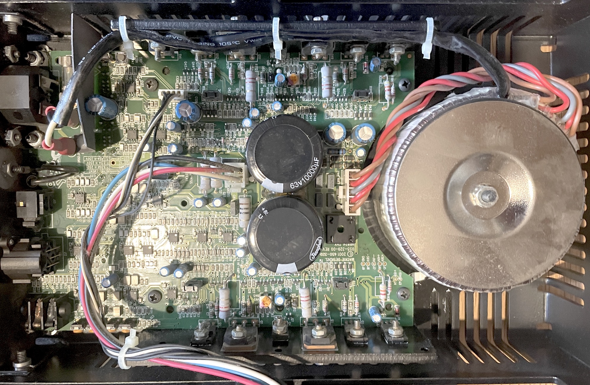
Yet to open it up and see what i'm dealing with. I guess the first thing I need do is look at the power caps and fuses. After that, i'm out of ideas!


I'm a hobbyist - no problem building guitar amps and pedals, but my diagnostics and repair game is pretty basic.

Any guidance would be appreciated.
 
Picture update. Back chassis removed for inspection.

Caps pass a quick visual inspection, fuse looks intact. Trafo connections all look rock solid. Not seeing any heat damage on components, didn't smell anything funny at the time of failure either.

9Afyz2h.jpg


I'm all ears for what to try next :)
 
Thanks Khron.

OK, THX board is what I have...

Based on the a similar fault that follows the HR624 variant (found via a couple of vids on Youtube), the HR824 equivalent component would be C116 or C117. Makes sense that if either of these paths failed, the power would go too.

f4Lh6SF.png


But i'm not 100% confident. This schematic is 10x more complicated than the classic guitar amp schematics i'm usually trying to follow.

Maybe best to leave this one to the pros.
 
I'm from the same background, and I had a similar reaction after looking through the schematics :) I would check the voltages to ground from either side of those two caps, to get a general read on the power supply voltages. If one of those is horked, that's likely an easier/cheaper fix, unless the power transformer is the culprit. (edit: 35vac on pin 3 of BR1 too)

Service manual if you haven't found it already: Download Mackie HR824 Service Manual | ManualsLib

Mackie doesn't just put humor in their user manuals! From pg 15 of the test procedures section:

"J5 is your time portal vortex to another realm of audio excitement."

"Use crocodile (alligator) clips, or better still, use them little hook
things."
 
Last edited:
Back to my prior post. The Youtuber with the power-up problem on his HR624 misquoted the cap number on the board (from my observation of the location vs the number on the HR624 schematic).

Seems the problem cap, if his is the same problem translated to a HR824, is actually C107.


UZlDE8W.jpg


Anyway, still not 100% confident, but still having fun trying to work it out :)
 
15-20 years old? Electrolytic caps. Anything in a plastic-wrapped(I see blue and black in yours) aluminum can. I would order two sets and replace all in the dark unit first. Pay attention to dimensions width of can and leg spacing and order higher voltage ratings in order to approximate the size of the originals. Amazing the difference in size over 20 years!
In this sitch I do not component level troubleshoot to look for ONE bad cap to replace and then put them back in service because if one electrolytic cap is bad, the whole lot is giving notice. Fix a power issue and have them back on the bench in 6 months with a loss of high end, etc. And powering on/off or variacing the circuit trying to troubleshoot something with at least 15 year old caps is a waste of time on a working bench plus can further damage the components around the bad cap/s. A look over the solder side of the PCB for brown areas will show areas of heat, either over time or recently, which can further indicate some caps worse than others.
When caps dry they start being other components, usually resistance. The black cans can go short and blow the square rectifier nearby. A little can after a V regulator can do the same thing.
When you get to removal, I still prefer heating single legs and taking them out leg by leg and THEN desoldering. I have great re-working eqpt, but do not like sucking solder with the leads in as half of them have to be done leg by leg anyway.
Mike
 
I've been known to snip the component out and then desolder the individual legs. Some PC boards (not saying Mackie stuff specifically) have thin, easily damaged traces, which can lift when heat is applied while a leg is then lifted at an oblique angle. If the existing component is sacrificial, and I have the replacement ready, I'll remove enough of the component itself in order to free up the legs independently. Sometimes they used glue under/around a component, to keep it in place during manufacturing...

Just my .0002. I agree with shotgunning the electrolytics as best practice, but replacing C107 initially looks to be the one to try first.
 
Last edited:
I got a pair of HR624 really cheaply several years ago because they would not turn on. It was a shorted cap in the auto circuit. I don't remember if it was C107 pointed out above, but if not it was something in the vicinity.
One of them isn't turning on again, and I am considering just pulling the entire auto circuit out and have them just controlled by the front panel switch.
Anyone know how to find a matching part number for the switch? The mechanical latch wears out over time and the switch won't stay latched in position.
 
Back to my prior post. The Youtuber with the power-up problem on his HR624 misquoted the cap number on the board (from my observation of the location vs the number on the HR624 schematic).

Seems the problem cap, if his is the same problem translated to a HR824, is actually C107.


UZlDE8W.jpg


Anyway, still not 100% confident, but still having fun trying to work it out :)
I would check you are getting all the AC voltages from the transformer, then check the DC voltages from the rectifiers first. The service manual test procedures show all the test points. If you have the speakers disconnected to get at the main board then use dummy load resistors - if you’re not putting signal through it’s safe to use 5W wire wound resistors - 8 ohm for the tweeter and 4 ohms for the woofer - use clip leads and plastic bag the resistors to make sure they don’t touch anything and short out. If you are getting all of those voltages then your problem could lie in the power mode switch on the rear or it’s associated circuitry - this if set to “auto” requires audio to switch on the speaker, if set to “on” then this will not leave you waiting for signal - this has had me getting phone calls from people saying their 824’s are faulty. Flick the slide switch back and forth a few times to ensure it’s not intermittent and leave it “on”. The front panel switch should then be turned on. There is also a thermostat safety shutoff switch (Listed as TH1: part# 67F070) which if it comes on shuts down the speaker - these can fail. Op-amp U12 if it fails (IC NJM4560M) can shut down the speaker - pin 1 needs to be low for power on to occur. The service manual schematics and board diagrams will show where these are located.
(This is related to your HR824 not the 624)
 
C107 replaced... C107 not the problem.

I think i'll take this to a tech and get it repaired, recapped in the process. Probably a bit too advanced for my skillset.
 
Hang on - I spoke too soon - it did fix the problem! I forgot it takes a full five seconds from flicking the switch to powering up. I was shutting it down too fast as a precautionary.

There you go - best 30 cents I have ever spent!

Che 1, Mackie 0.


But noted it's time for a full re-cap. I think i'll save that job for summer.
 

Latest posts

Back
Top