Hey-
I did a lot of searching on the web and various forums trying to find details on the MK012 “D*****” mod. I have the Recording article, but I had hoped to find more info on individuals’ experiences with the mod as well as updated info, as the article is a few years old now. I found some helpful stuff, but not the all inclusive source that I had hoped for.
This post is an effort to fill the gap I found in my searches, and to hopefully pay back a little of the wealth of info I have garnered from the Lab. Will someone please let me know if I am wrong in any details or if I am violating any copyright law. Please.
Part sources and part numbers for this mod are included throughout this post where they are relevant. I would print them all together, but it might resemble the list in Scott D*****’s article, and I wouldn’t want anyone to think that I was plagiarizing him.
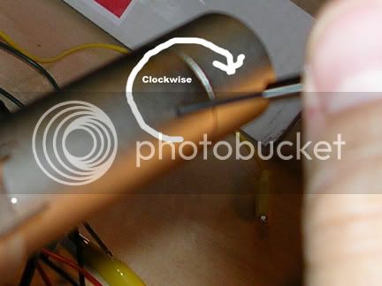
Here is an image of the casing of the MK012. Please note that you drive the screws INTO THE BODY OF THE MICROPHONE!!!!! to release the board. A very small, big mistake here can start your modding experience off on a negative note.
Okay, there are 3 screws to turn IN... once you’ve done this, push on the plastic pad at the top of the body and simultaneously pull on the XLR connector at the bottom of the body, and wrangle the board out of the casing.
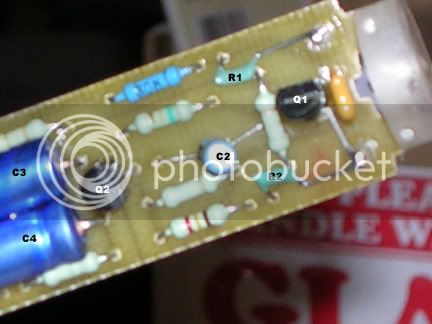
Here is a pic of the board from one of my mics with all the original components:
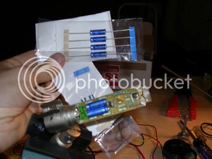
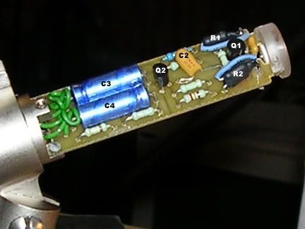
Here is a shot of the parts I bought that I didn’t need to (they are all caps.) Apparently, my mics are some of the newer releases that have better components based on Scott D*****’s mod article, even though they were purchased 4 years ago. The only parts I didn’t replace are the blue vinyl coated caps C3, C4 (both Digikey part number4073PHCT-ND), and C5 (4047PHCT-ND), because they were the same as the caps I bought from Digikey. You won’t see C5 in any of my photos. It’s the big blue cap on the back side of the board from most of the components. There are only 4 parts soldered on that side, so if you need to replace it on your mic, it will be easy to determine which cap it is.
h
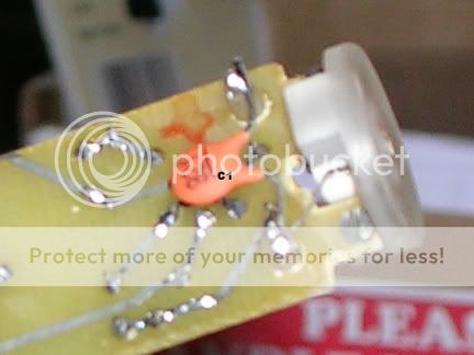
The first part I replaced was the capacitor labeled C1 (Mouser part number 140-50P2-821K-RC). I started here because it was an easy swap. Check this pic:
I put an 820pF ceramic disc cap in as replacement for the stock cap. Scott D***** recommends a COG ceramic cap, which I would have used, but I had trouble sourcing them when I was in the mood to search.
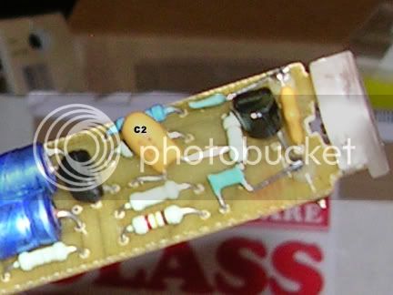
Next was C2 (Mouser part number 74-199D25V10-E) another easy tradeout...
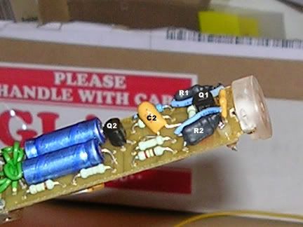
Okay, now it gets a bit more difficult. Swapping out the FET labeled Q1 (an npn transistor 2SK170BL from http://www.tech-diy.com/smallsignal.htm under Small Signal Transisitors and JFET's ) is not such a big deal, but you should do it in conjunction with replacing R1 and R2 (both Mouser part number 588-MOX-200001007JE). This is the Big Tangle, in my opinion. Scott D*****'s article suggested putting in 2-1G ohm resistors in series, so that’s what I did. The part number above is for the 1G ohm resistors I used. Pricey.
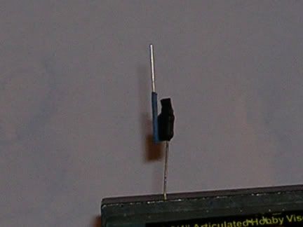
I soldered my resistors together and I wrapped them in heatshrink tubing...
Here they are in place.
I had to bend and push things so that they would fit within the original profile. There is no room for give in this mod. The first time I tried it, the resistors 1 and 2 were scraping the sides of the casing and it just didn’t work. Keep everything as low profile as the parts you haven’t changed yet, and you should be fine.
Lastly, I replaced the transistor Q2 (Digikey part number 2N5087-ND.)
Here’s an important note I think. If you look at the image with all the original parts in it, you’ll notice that by the time I finished this project, both of the FET’s flat sides were oriented 180 degrees away from their original positions. This is one of the problems I had when trying to perform this mod by the Recording article. The photos in that article showed replacement components alongside original components. In regard to transistors, that can be very misleading. I read forum posts that said “just install it like the photo”, which is exactly right in regard to Q1, but exactly wrong in regard to Q2. This is also one of the points on which I would really appreciate someone correcting me if I am wrong. My conclusion is based on the schematic in the Recording article and the voltage readings listed there.
Lastly, here’s a pic of all the parts I removed from one of my mics. I am just putting this here so you can, hopefully, get an idea of the scale you’ll be working on.
These mics sounded good before this mod and they sound good after. I’m posting this as a matter of disclosure, not as an endorsement of the modification. I have to spend time with changes before I can really offer a material opinion. The process however, is as described.
Please let me know if other, different photos would be helpful, and I will post reasonable requests to this thread
Best of luck.