


Dr Tony Balls
New member
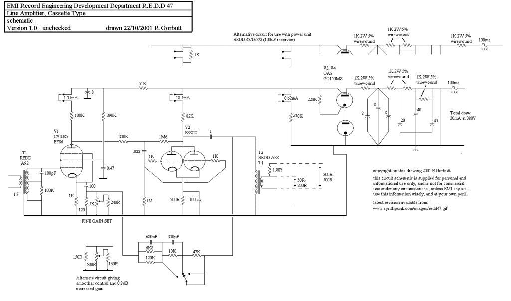
Hi all.....first time poster, long time lurker/knowledge sponge. I'm an accomplished builder in the guitar electronics world with over 60 tube amp/preamp circuits built and too many pedals to mention. That is all to say that i'm not a complete dummy/newbie to building but this one is a step outside of my normal comfort zone into the world of recording gear, specifically a mic preamp. I was asked by a friend if I had ever attempted a tube mic preamp and I decided to give it a shot by starting with the EMI REDD 47 circuit. As i'm sure you all know, there are many versions of the schematic floating around and I consulted many, but this was a good one that I used:
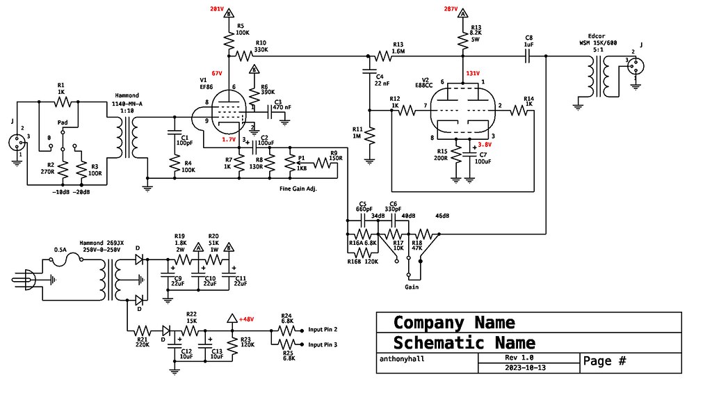
My thought was to try and simplify things a bit both technically and economically, at least for a test build. So for input and output transformers instead of opting for picier versions I tried the Hammond 1140-MN-A (1:10) and the Edcor WSM 15K/600 (5:1), respectively. I added an input pad, and I also simplified the power supply a bit, taking nods from the MILA-1 circuit, with a more simple full-wave rectified design that provides ~290VDC. My filament supply is AC, coming right of the secondary taps on my PT. Here's my resulting schematic with voltages:
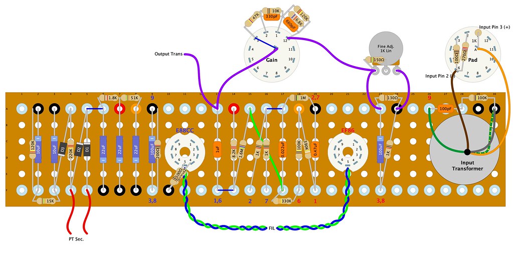
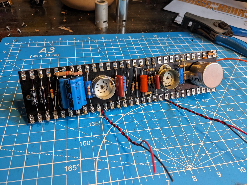
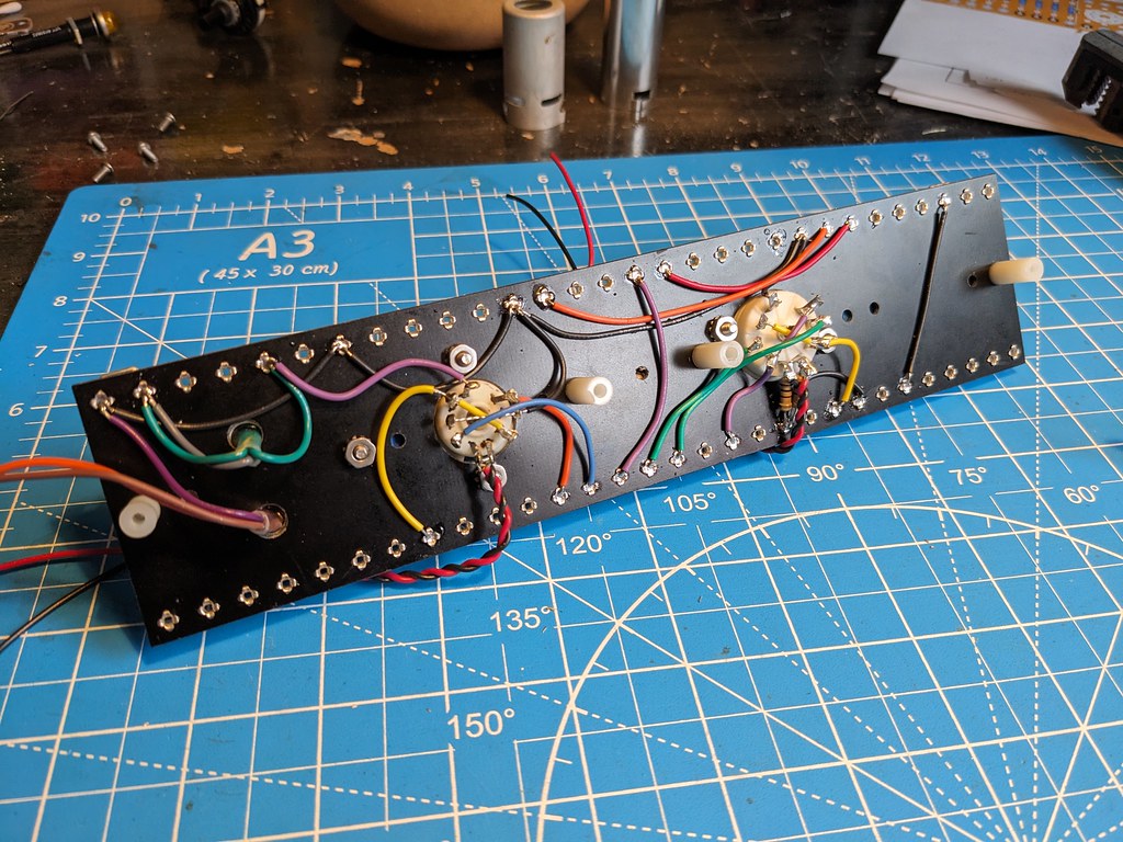
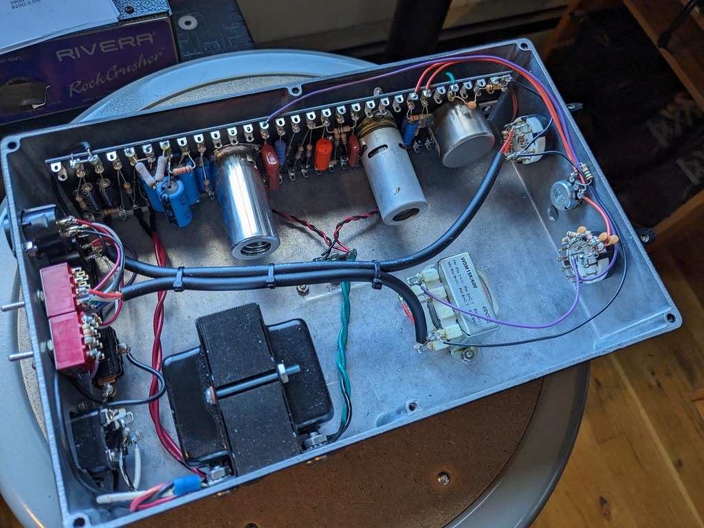
For the layout & construction I went with tagboard with almost all componentry mounted to it, including tubes and input transformer. My layout and pics of the build are here:
Anyway, here's where the problems start. Its passing signal and the controls seem to affect the signal as they should but the amount of amplification is very low. I'm just doing rough tests with a dynamic mic and a small guitar amp to verify that its working before testing it in studio but the signal level is much lower than the mic level alone without the preamp. Also the EF86 position is *wildly* microphonic. I've tried it with two tubes of different manufacturer and the problem persists. It even happens without an input signal connected. I've built plenty of EF86 amps before and know that they can have microphonic issues but never have I encountered something like this. It will self-oscillate and grow into a feedback-like sound in higher gain settings.
So after unloading all of that info....can anyone shed any light on where my problems might lie? I've gone over the schematics and my layout may times and everything looks correct, but maybe i'm placing sensitive components in the wrong place without realizing it. Or maybe my whole construction technique is problematic. ANY HELP IS APPRECIATED!
My thought was to try and simplify things a bit both technically and economically, at least for a test build. So for input and output transformers instead of opting for picier versions I tried the Hammond 1140-MN-A (1:10) and the Edcor WSM 15K/600 (5:1), respectively. I added an input pad, and I also simplified the power supply a bit, taking nods from the MILA-1 circuit, with a more simple full-wave rectified design that provides ~290VDC. My filament supply is AC, coming right of the secondary taps on my PT. Here's my resulting schematic with voltages:
For the layout & construction I went with tagboard with almost all componentry mounted to it, including tubes and input transformer. My layout and pics of the build are here:
Anyway, here's where the problems start. Its passing signal and the controls seem to affect the signal as they should but the amount of amplification is very low. I'm just doing rough tests with a dynamic mic and a small guitar amp to verify that its working before testing it in studio but the signal level is much lower than the mic level alone without the preamp. Also the EF86 position is *wildly* microphonic. I've tried it with two tubes of different manufacturer and the problem persists. It even happens without an input signal connected. I've built plenty of EF86 amps before and know that they can have microphonic issues but never have I encountered something like this. It will self-oscillate and grow into a feedback-like sound in higher gain settings.
So after unloading all of that info....can anyone shed any light on where my problems might lie? I've gone over the schematics and my layout may times and everything looks correct, but maybe i'm placing sensitive components in the wrong place without realizing it. Or maybe my whole construction technique is problematic. ANY HELP IS APPRECIATED!
")
