Hello all.
I have decided to go ahead and give this (bass) preamp a go as I believe the need for a bit of grit is approaching soon. I have looked around for advice/analysis as much as possible but I'm still new to the more in depth side of electronics and was hoping for some help.
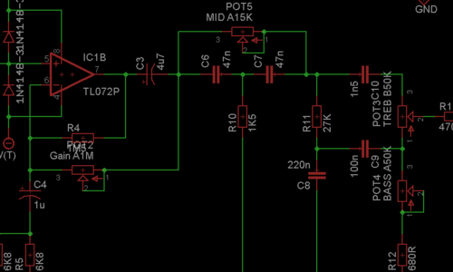
I have attached the full schematic below for reference.
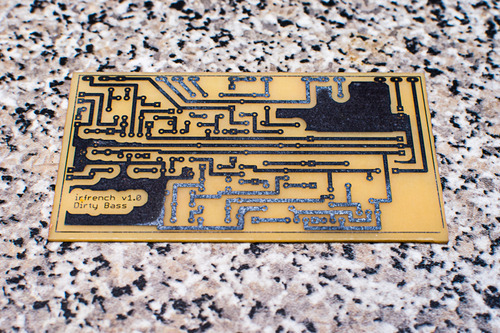
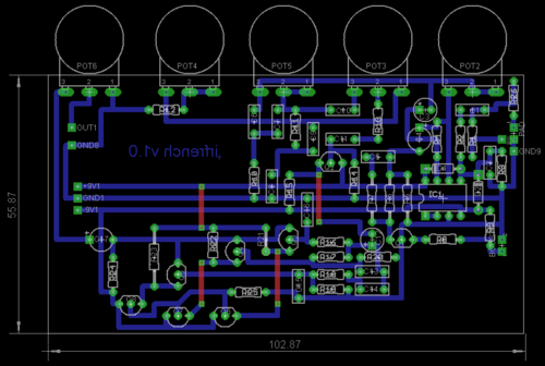
I have created a single sided board layout (with only a few jumpers) which I am pretty happy with:
I have a couple/few questions so if anyone can help I'd be really grateful.
1. I have never been sure of pot wiring, but as I'm using board mounted pots I was hoping that they'd be right (first time? :-[). Do these look right? Sorry to ask...
The original schematic does not show pot pin numbers - so I have done them like so with the intention of clockwise being 'more' (I'm confident about the volume one :") so I've only shown the others):
so I've only shown the others):
2. The boost switch looks to just be a connection to ground (switched via jack socket if pedal is inserted). Have I totally misread that section!?
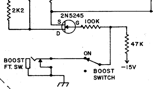
3. The next part is the one where I guess I'll have to do some trial and error, but if anyone can steer me in the right direction I'm all ears! - Transistor substitutes...
I cannot seem to find a 'normal' source for the original 2n5425, I have assumed a standard 2n5457 would be fine here?
The MPSA18 can still be had but as an option would the 2n5088 be suitable?
The most intriguing part of the circuit is the 'ladder' of PNP transistors at the end, to my untrained eye it looks like the signal is split and this is where compression/clipping occurs. I'm hoping to be able to get some MPS8598/8599s but if that proves unfruitful - again would a simple 2n5087 be suitable?
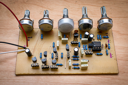
Once I've got it all working OK I'll be sure to share the project as it seems to be a desirable way to get a gritty bass sound.
I'm sorry there are so many questions.
Ian.
I have decided to go ahead and give this (bass) preamp a go as I believe the need for a bit of grit is approaching soon. I have looked around for advice/analysis as much as possible but I'm still new to the more in depth side of electronics and was hoping for some help.
I have attached the full schematic below for reference.
I have created a single sided board layout (with only a few jumpers) which I am pretty happy with:
I have a couple/few questions so if anyone can help I'd be really grateful.
1. I have never been sure of pot wiring, but as I'm using board mounted pots I was hoping that they'd be right (first time? :-[). Do these look right? Sorry to ask...
The original schematic does not show pot pin numbers - so I have done them like so with the intention of clockwise being 'more' (I'm confident about the volume one :
so I've only shown the others):
2. The boost switch looks to just be a connection to ground (switched via jack socket if pedal is inserted). Have I totally misread that section!?
3. The next part is the one where I guess I'll have to do some trial and error, but if anyone can steer me in the right direction I'm all ears! - Transistor substitutes...
I cannot seem to find a 'normal' source for the original 2n5425, I have assumed a standard 2n5457 would be fine here?
The MPSA18 can still be had but as an option would the 2n5088 be suitable?
The most intriguing part of the circuit is the 'ladder' of PNP transistors at the end, to my untrained eye it looks like the signal is split and this is where compression/clipping occurs. I'm hoping to be able to get some MPS8598/8599s but if that proves unfruitful - again would a simple 2n5087 be suitable?
Once I've got it all working OK I'll be sure to share the project as it seems to be a desirable way to get a gritty bass sound.
I'm sorry there are so many questions.
Ian.