spring reverb analogue predelay "design"

GroupDIY Audio Forum

Help Support GroupDIY Audio Forum:

This site may earn a commission from merchant affiliate links, including eBay, Amazon, and others.
Joined
Feb 27, 2007
Messages
23
Location
paris (please forgive my english)
hi prodigy folks, i am new to this board, and not a very experienced electonician. anyway i am trying to uplift my skills, develloping little ideas without pretention. and i have to mention that i never lived in an english speaking country so please fogive my english :)

by now, i want to draw a schematic for a reverb unit/guitar pedal without any digitizing of the audio signal. in fact, more than drawing it from A to Z, i am trying to upgrade this spring reverb schematic :
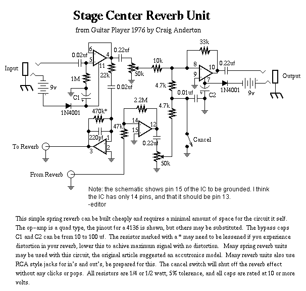
screverb.gif

http://www.montagar.com/~patj/screverb.gif


the main problem that i have is that, as far as i am aware, reverb predelay is fixed and dependent of the spring properties. so i want to put a spring with very short "intern" predelay, and put an analogue deelay line before sending signal to the imp adapting opamp circuit that's before "send to spring" jack output.

while reserching, i found about analogue deelay chips, called BBDs. so here is my question : has anyone experienced working with these? do anyone know a simple schematic that would have a good audio frequency response?

but maybe someone knows a better way to do what i want without the use of digital... it's kind of a chalenge i ask myself


thanks a lot to thoose who will kindly spend time answering/helping me :)
 
I published a kit article for a BBD delay line back in 1976 (Popular Electronics). That kit was based on Matsushita MN3001 but I have also done designs based around Reticon SAD1024. I would do a search for either of those part numbers to find designs. Mine are not on the web AFAIK but I have seen some effects pedals using BBD published.

Regarding the spring reverb a little pre-delay does wonders for increasing the time until the first return giving a sense of a larger space, I would also consider changing the spring driver to a current source from a voltage source.

JR
 
Another option is to use an old 3-head tape deck with some arrangement to vary the capstan motor speed and/or the spacing of the record and reproduce heads. This is to control the delay time.

It sounds like a Rube Goldberg lashup (and it is) but old tape machines can be had for cheap.
 
The spacing of the record and reproduce heads are fixed in most of the tape decks, since it is mostly "one head" with two different areas in it. But varying the speed works well!
I have tryed this on many old tape decks and its interesting how strong the sound between different models differs!
I would non consider to archive "studio quality" but its cheep and fun. Depending on your likes it can be a very usefull effekt. Not only for predelay, but if you add some litte feedback (or even more;) one can have cool tape echos.
 
[quote author="NewYorkDave"]Another option is to use an old 3-head tape deck with some arrangement to vary the capstan motor speed and/or the spacing of the record and reproduce heads.[/quote]
thanks for this nice suggestion.
but i am afraid this is not what i am looking for because it is too big to fit in a pedalboard, even more considering the room taken by the spring...


[quote author="JohnRoberts"]I published a kit article for a BBD delay line back in 1976 (Popular Electronics). That kit was based on Matsushita MN3001 but I have also done designs based around Reticon SAD1024. I would do a search for either of those part numbers to find designs. Mine are not on the web AFAIK but I have seen some effects pedals using BBD published.[/quote]
I found that it was used in ibanez deelays, mainly. but the schematic is much to complicated for me, and i don't want to build something i don't understand. electronics is not lego...
the following schematic is from the mn3001/mn3002 datasheet :
http://twin-x.com/groupdiy/displayimage.php?pos=-996
it is quite clear to me, but do you think it will sound great?
and it was designed for mn3001 or 3002, do you thnik there will be a problem if i use mn3005 instead, in order to produce longer predelays?


[quote author="JohnRoberts"] I would also consider changing the spring driver to a current source from a voltage source. [/quote]
can you explain this because i do not understand :oops:
 
[quote author="bergmann disney"]

[quote author="JohnRoberts"] I would also consider changing the spring driver to a current source from a voltage source. [/quote]

can you explain this because i do not understand[/url][/quote]
The spring-input-coil is placed 'in' the feedback-network of the driver i.s.o. being simply fed from the output-voltage of the driver.
The former is 'current steering' & the latter 'voltage steering'. The former forces a certain current through the coil, thereby compensating (or 'ignoring') the increasing resulting impedance of the coil for higher frequencies ('w*L')

For example have a look for the current-thing here, as done for more bandwidth:
http://www.d-r.nl/dnrsite/Service Parts/Reverb-Spring-Service.PDF
(look for the coils marked '300 300' on page 2)

Note that the voltage-driven thing might sound more familiar and/or desirable/or 'warmer' (...); higher BW isn't always better.
But doing it the current-way you could always still remove some highs later on. Boosting them (when for instance voltage-steering was used) will give a noise penalty.

Bye,

Peter
 
Yes, a 3005 could be substituted, I never used one so I don't have personal experience. If longer it will be noisier.

That schematic doesn't show the whole circuit. BBD delay chips require two phases of square wave clock (usually generated by cmos d-type FF), input filtering to reduce aliasing caused by sample rate, and output smoothing filter to remove clock noise, etc.

Schematics you have found are probably pretty close to minimum you need. You might save one or two opamps used to vary clock frequency for effects. Maybe this weekend I’ll scan in my old article but I sold the copyright to Popular Electronics 20 years ago so I don't have the right to publish. FWIW my simple delay used 2 CMOS ICs in the clock circuit and several opamps sections for input and output filters, with a power supply regulator IC.
=====

There have been other threads here and elsewhere about driving spring reverbs. You can make your voltage source driver look like a current source by putting the reverb send coil in place of the feedback resistor in the driver opamp (one from opamp output to minus input). Explaining all the details of this would take more words than I have to offer right now.

JR
 
[quote author="JohnRoberts"]Explaining all the details of this would take more words than I have to offer right now.

JR[/quote]
I may have typed a few of these words for you already, see above :wink:

(we'll have been typing at the same time)
 
[quote author="JohnRoberts"]Yes, a 3005 could be substituted, I never used one so I don't have personal experience. If longer it will be noisier.[/quote]
good new.

[quote author="JohnRoberts"]That schematic doesn't show the whole circuit. BBD delay chips require two phases of square wave clock (usually generated by cmos d-type FF), input filtering to reduce aliasing caused by sample rate, and output smoothing filter to remove clock noise, etc.

Schematics you have found are probably pretty close to minimum you need. You might save one or two opamps used to vary clock frequency for effects. Maybe this weekend I’ll scan in my old article [/quote]

for the clock, i was thinking about using mn3101 related clock generator. i have the datasheet too so i don't think it will be a problem to know how to use it.
but if you know another way to generate proper clock, it will be a hell of a help because these chips are getting hard to find today... so that would be cool if you scanned your article to help me, plus i can see how you did other necessary modules (filtering, etc.) if you do.
but i don't want to be heavy about it...

[quote author="JohnRoberts"]There have been other threads here and elsewhere about driving spring reverbs.[/quote]
don't bother, i will check about it by myself and then ask precise questions if i feel the need
 
[quote author="bergmann disney"]while reserching, i found about analogue deelay chips, called BBDs. so here is my question : has anyone experienced working with these? do anyone know a simple schematic that would have a good audio frequency response?
[/quote]

There's a good deal going on BBDs here :
http://cgi.ebay.com/NEW-ICS-MN3007-PANASONIC-DIP8_W0QQitemZ150107036762QQihZ005QQcategoryZ50912QQrdZ1QQcmdZViewItem

at the moment, and you can find appnotes here :
http://www.datasheetarchive.com/search.php?q=MN3007&sType=part&ExactDS=Starts

(The third item in the list) The biggest enemy with BBDs is noise, and typically one compresses the audio before the BBD and expands it afterwards (The NE570 is a good choice here). The SAD1024 is a bit of a tricky beast as it has a very definate "sweet spot" in the input biassing, and this spot changes according to the clock frequency. The MN chips have a bit more latitude in this respect. A wonderful example of trailing edge technology (I'm even tempted to buy a few of the ebay ones myself for nostalgias sake)
M
 
[quote author="mobyd"]There's a good deal going on BBDs here :
http://cgi.ebay.com/NEW-ICS-MN3007-PANASONIC-DIP8_W0QQitemZ150107036762QQihZ005QQcategoryZ50912QQrdZ1QQcmdZViewItem[/quote]
yes, good new :grin:
i already had this datasheet, but thank you for this to anyway.
is noise so loud??

mediatech, i am going to read your article tonight.


i found this other app circuit, with pre and post chip filtering :
http://twin-x.com/groupdiy/displayimage.php?pos=-1000
would it be enough to get good audio results? (i think that both clock pulse signal must be square, and CP2 must be boolean opposite of CP1, i mean : CP1=0 when CP2=1 and CP1=1 when CP2=0, am i right??)
 
Yes, on the clock. A good way to generate the clock with 50% duty cycle is to use a D-type FF like a CD43013, configured as a divide by 2. The Q and Qbar outputs give you the two phases. So use one of several any shape clock generators running at 2x desired clock then clean it up with FF.

Noise floor of BBDs are a function of delay time. The lower the clock frequency the more time the individual samples have to degrade. S/N can be pretty poor (<50dB). I routinely used 2:1 companding in more critical designs, using OTA based gain elements before dedicated chips like NE570 and 572 were available. I also combined HF pre/de-emphasis with the companding. Resist the temptation to put the expander after the spring as the reverb tail will interfere with proper decoing, unless you're willing to mess with your detector circuits in expander and willing to experiemnt as this is not trivial.

In recall one very difficult design where I combined pre/de-emphasis, anti-alias, and anti-image filters, into a multi-pole Chebychev alignment. I put the under damped (boost before roll-off) stages before the BBD, and the real pole, tweaked to line up with the bottom of the de-emphasis pole right at the very output to squelch the HF clock garbage present in the output, followed by an overdamped section. Circa '70s opamps weren't very happy trying to handle those clock artifacts in active filter circuits.

That design is lost to the bit heap of time, but I recall using a crude filter design program I wrote in BASIC for my old H-11 computer that printed out the frequency response using its tab command. I don't miss those good old days.

JR
 
Ok.
i have been working a bit on it since my last post.

i found MN3205 chips for sale online at a correct price, far better than MN3005. so i tried to draw something with this chip, here is the new shematic i came up with :
http://twin-x.com/groupdiy/displayimage.php?pos=-1002
what do you think of it?
(i must appologize, yes, it's hand drawn... i did my best and hope it will be good enough for you. by the way, could someone advice me on a good software i could get to draw my shematics and/or my PCBs ???)

datasheet says signal/noise ratio is 73dB for MN3205, do you still reckon i will need to make a kind of dolby comp/expand to not be annoyed by this chip noise?

i also found MN3102 clone (related clock driver to MN320X series) for quite cheap price, so i was wondering if it would be really necessary to designe a clock driving circuit with astable NE555, even if it will cost a bit more to use 3201...


and thanks for sugesting a postreverb dynamic control, i did not think of it till now... i often gate/comp reveb returns when i mix a song because i think it kind of "enhances" the reverb results, and i may think about adding such a module to my starting schematic.
but i'll do it later, i must do with this damn predelay before :?
 
I'm not familiar with any of the newer BBD parts but one thing to check about the S/N spec is what clock frequency it is specified at. Noise gets worse at lower clock frequencies so check noise spec for the frequency you will be operating at.

If you are thinking of using compression/expansion to vary reverb tail decay time and use something like a NE570, you will have a second gain element and rectifier available.

JR
 
S/N is 67 dB at maximum deelay time (=minimum clock frequency). so, dolby-like noise reduction needed??

edit :
a few more searches and it looks like mostly everybody compands their signal when sending it throuhgt a BBD. so i gess i am going to have to do it.

------------------
would you think it will be better compressing before or after anti-aliasing input filtering?
and expanding before or after output low-pass?


did you look at the filters i placed before and after the chip, on the schematic??
 
[quote author="bergmann disney"]S/N is 67 dB at maximum deelay time (=minimum clock frequency). so, dolby-like noise reduction needed??

edit :
a few more searches and it looks like mostly everybody compands their signal when sending it throuhgt a BBD. so i gess i am going to have to do it.

------------------
would you think it will be better compressing before or after anti-aliasing input filtering?
and expanding before or after output low-pass?


did you look at the filters i placed before and after the chip, on the schematic??[/quote]

The S/N basically comes down to what is acceptable to you. 67 dB is better than a cassette deck with no NR, but not up to modern recording media.

The compressor and expander gain element can be placed pretty much anywhere, but you may want to pay careful attention to where you pick off the detector circuitry since frequency response differences between the two can cause mistracking. Sometimes it's worthwhile to bandpass down the side chain to make it less sensitive.

Yes, I saw the filter but I'm not going to confirm the calculations.. that's a little too much like work. .

JR
 
[quote author="JohnRoberts"]The compressor and expander gain element can be placed pretty much anywhere, but you may want to pay careful attention to where you pick off the detector circuitry since frequency response differences between the two can cause mistracking.[/quote]
ok, i'll have to dive deeper in NE570 datasheet coz by now, the realization of it looks pretty misty to me.
but i think i understand the general idea of what you said. what i wan't from this operation is to be as transparent as possible, regarding to the sound.

[quote author="JohnRoberts"]Yes, I saw the filter but I'm not going to confirm the calculations.. that's a little too much like work. [/quote]
i was not asking for such a thing :wink:
but sometime a quick glance at a shematic shows enormous errors... if it looks alright, then i am confident in my calculations.

-------

[quote author="mediatechnology"]
http://www.coolaudio-semicon.com/products.html[/quote]
nice link, thanks
but do you think these copy chips (exept clock driver...) will sound as the original ones?

[quote author="mediatechnology"]Needless to say some appear to be shameless copies and theft of IP in the cases where patented product is still being produced by the original vendor.[/quote]
beringher philosophy... :? :?

[quote author="mediatechnology"]One trick I used with the SAD1024 and I don't know if it works with the MN3XXX is to put a balance pot at the two output phases of the device. IIRC you have some 200K loads and then two resistors summing in to the output. In the DynaFlanger we did at MicMix I balanced those two signals and then used a three transistor NPN Wilson current mirror. I took the output from a resistive collector load. I'll see if I can find the schematic you might want to try that. It reduced the pedestal noise (the two output phases are interleaved) and distortion.[/quote]
nice results, but i cannot visualize the schematic you mean. i'll do a search about wilson current mirror and test it with my BBD chip.
 
Yes, that output trim is correcting for a Vg-s error in two output source followers. The noise energy is clock frequency and higher so generally not a big problem unless running clocks down into audio frequency range. If you want to be real tweaky it probably should be two current sources being varied. I've never used a trim for that in production. This clearly needs to be filtered out of expander sidechain.

BTW, the Matsushita parts are a different polarity than Reticon so in theory should be run from a minus suppy, but as long as supply is regulated and clean a positive single supply is OK.

JR
 
[quote author="JohnRoberts"]This clearly needs to be filtered out of expander sidechain.JR[/quote]
do this mean : BBD -> expand -> low-pass ???


anyway, i found this NE570 companding schematic :
http://twin-x.com/groupdiy/displayimage.php?pos=-1003
and checked it regarding to the NE570 datasheet.
it seems allright, providing 2:1 compression and 1:2 expansion.

the only thing i am not fixed about is the rectification caps value : is 1µF providing attack/release times correct for audio signals? (n the datasheet typical test circuit they put 2,2µF)
note that datasheet says : G(t)=(Ginitial-Gfinal)e-(t/T) ; with T=10KxCrect, but i don't understand anything to this formula...
 

Latest posts

Back
Top