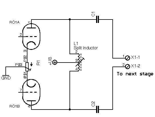
> theory of operation and suggestions about establishing a loadline for the L-C coupled circuit: what does the valve see
Are you building "good" or "bad"?
In a "good" design, at all frequencies of interest, the inductive and capacitive reactances are "negligible" (high and low respectively) compared to the resistances (plate and load).
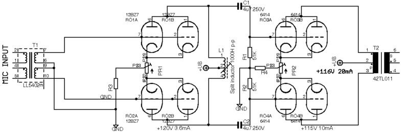
Example: for 5K plate resistance, 100K load resistance, if the inductive reactance is greater than 4.76K at the lowest frequency you must pass, it won't be a big problem. Say 30Hz? Then you want more than 25.3H of inductance per side. 26H*30Hz*6.28= 4.9K, a slight loading on your 4.76K resistance. Response falls almost 3dB. At 300Hz the choke acts like 49K, quite negligible compared to plate and load resistance.
There may be a correction for the two sides being coupled. My sense is that it has to work per-side, and the cross-couple is a minor change.
In practice, your choke value is set by the choke you can buy, which is never the one you calculate.
In this case: it looks like a 10KCT:8 output transformer minus the 8 winding. We could get a somewhat better choke if we re-allocated the 8 ohm winding space/cost to the 10K winding; the cost of just taking a stock OT compared to a custom choke suggests just buying a transformer rated for your power and frequency.
The caps have to have lower reactance than the resistances in series, 105K. 0.1uFd is handy. Seems to give 17Hz corner.
You can work the math (or simulator) and find that this combination is down 3dB at 35Hz. You can wear your pencil to the bone finding other values to give 30Hz. But the real question is balance: in today's world, a fat cap may be cheaper, or easier to find, than a fat choke. And for one-off, an over-fat cap may be cheaper than the brain-strain to "optimize" a thing you only build once. I threw 0.5uFd in there and got -3dB at 30Hz, 5uFd gave 29Hz... with enough cap overkill, it comes down to the choke you can find.
The DC "load line" is, as NYD said, just choke resistance. If your choke is any darn good, DCR is small. If it is high inductance, it will be significant. Often 1/10th of the intended impedance. A "10K" winding with good bass response could be as much as 100 ohms DCR. If the tube flows 20mA, there is a 20V DC drop. If the B+ is 200V, then the tube really only feels 180V. Or you could jack the B+ to 220V. DCR rarely "ruins" performance, but it can be one of many "little losses" which add up to missing your goal. My "13W amp" made 8W because of a lot of little losses. On stage, who would know? On test-bench, I "didn't meet spec".
This all assumes everything is "linear", or near-enough to rock. If "X1" is a class B tube grid, then "load" is 100Meg over part of the cycle but 1K on peaks. Such a load line is severely kinked. Hockey-stick.