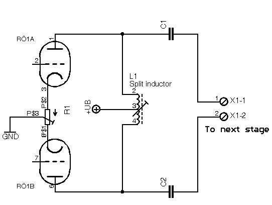
How to find the tube loadline in an L-C coupled circuit

GroupDIY Audio Forum

Help Support GroupDIY Audio Forum:

This site may earn a commission from merchant affiliate links, including eBay, Amazon, and others.

Val_r

Well-known member
Joined
Jun 5, 2004
Messages
306
Location
Naples, Italy.
Hi,

Interested in the theory of operation and suggestions about establishing a loadline for the L-C coupled circuit: what does the valve see, analogies with the R-C coupling, any readings to suggest?

Thanks,
Val


:green:
 
Do you mean L load and C decoupling cap to the signal load, or LC tuned circuit? :green:
 
[quote author="Wavebourn"]Do you mean L load and C decoupling cap to the signal load?[/quote]
Yes

[quote author="Larrchild"]

You can do it 2 ways.

Parallel coupling, which looks just like an audio output transformer with a primary and secondary, except they are mutually-coupled coils in proximity to each other.

Or series coupled or "Pi" network, which is a capacitive coupled series inductor with a cap to ground on each end.
[/quote]

This is what I had in my mind

I was trying to figure out what inductance does each rail see, and what is the technique to establish a loadline, or you should consider it as if it was a primary of a transformer, so working out with the impedance calcula.

split-ind.jpg


Any suggested readings about this topic?

Thanks,

Val

:roll:
 
Lar' just assumed you meant at rf.

so sorry.

cause you mean parafeed! (sort of)

ok

lemme look.

ok, closer to a transformer primary than a pure resistive load, but not quite.
Someone with the smarts we need... take over!

We know this, voltage will change less than across the resistor.
 
[quote author="Larrchild"]
cause you mean parafeed! (sort of)[/quote]

I thought that parallel feed meant to decouple the DC BEFORE the transformer, so the two caps should lay between the anodes and the primary...

I was meaning LC coupled because it is like a R-C coupled stage but with L instead of R (which allows me to have a very low resistance on the load each tube will see) correct me if I'm wrong.

T.Y.
 
I agree, thats a great way to couple one push pull stage to the next. sorry it's not parafeed but i'm looking for the word. Heising?

Anyway, voltage swing (DC) will be way less than thru a plate R.
 
that circuit fragment reminded me of this

http://www.geocities.com/TimesSquare/1965/pp3cx300.html
 
Look for information on "impedance coupling." That's what it's called.

The DC loadline is easy; it's just the DC resistance of the choke. The AC loadline is drawn using the choke's inductive reactance + DCR in series, in parallel with the series combination of coupling cap reactance and the load. Naturally, this is frequency-specific. For high frequencies, include the distributed capacitance of the choke in parallel with its inductive reactance.
 
In such case your load line depends on the load resistance (i.e. on input resistance of what you connect to output), with B+ in center.
 
> theory of operation and suggestions about establishing a loadline for the L-C coupled circuit: what does the valve see

Are you building "good" or "bad"?

In a "good" design, at all frequencies of interest, the inductive and capacitive reactances are "negligible" (high and low respectively) compared to the resistances (plate and load).

Example: for 5K plate resistance, 100K load resistance, if the inductive reactance is greater than 4.76K at the lowest frequency you must pass, it won't be a big problem. Say 30Hz? Then you want more than 25.3H of inductance per side. 26H*30Hz*6.28= 4.9K, a slight loading on your 4.76K resistance. Response falls almost 3dB. At 300Hz the choke acts like 49K, quite negligible compared to plate and load resistance.

There may be a correction for the two sides being coupled. My sense is that it has to work per-side, and the cross-couple is a minor change.

In practice, your choke value is set by the choke you can buy, which is never the one you calculate.

In this case: it looks like a 10KCT:8 output transformer minus the 8 winding. We could get a somewhat better choke if we re-allocated the 8 ohm winding space/cost to the 10K winding; the cost of just taking a stock OT compared to a custom choke suggests just buying a transformer rated for your power and frequency.

The caps have to have lower reactance than the resistances in series, 105K. 0.1uFd is handy. Seems to give 17Hz corner.

You can work the math (or simulator) and find that this combination is down 3dB at 35Hz. You can wear your pencil to the bone finding other values to give 30Hz. But the real question is balance: in today's world, a fat cap may be cheaper, or easier to find, than a fat choke. And for one-off, an over-fat cap may be cheaper than the brain-strain to "optimize" a thing you only build once. I threw 0.5uFd in there and got -3dB at 30Hz, 5uFd gave 29Hz... with enough cap overkill, it comes down to the choke you can find.

The DC "load line" is, as NYD said, just choke resistance. If your choke is any darn good, DCR is small. If it is high inductance, it will be significant. Often 1/10th of the intended impedance. A "10K" winding with good bass response could be as much as 100 ohms DCR. If the tube flows 20mA, there is a 20V DC drop. If the B+ is 200V, then the tube really only feels 180V. Or you could jack the B+ to 220V. DCR rarely "ruins" performance, but it can be one of many "little losses" which add up to missing your goal. My "13W amp" made 8W because of a lot of little losses. On stage, who would know? On test-bench, I "didn't meet spec".

This all assumes everything is "linear", or near-enough to rock. If "X1" is a class B tube grid, then "load" is 100Meg over part of the cycle but 1K on peaks. Such a load line is severely kinked. Hockey-stick.
 
I had something like this on my mind, it is a mic preamp

tt.jpg


plate resistance of each 12bz7 rail is around 15K, split inductor is rated 1,000H plate to plate, so each rail RO1 and RO2 will see 125H (each rail sees 1/8 of total inductance)

So, with 51K load resistor, Xl is 39.27K at 50Hz, considering that this type of choke's dcr is about 10/15K, Xc is 680 ohms...
So my estimated AC loadline is 26.47K at 50Hz, 47.89K at 1KHz, 50.83K @ 20KHz.

Comments?[/quote]
 
(each rail sees 1/8 of total inductance)

wouldn´t it be 1/4? I mean, a 1000H inductor? Where would you get that? I think you need only a 500H one as 500 / 4 = 125H, and PRR sugests a much lower one, like a 10k primary of a transformer, that would be something like 160H, and you are using two triode sections on each side, so you could go even lower.
 
[quote author="rafafredd"]
(each rail sees 1/8 of total inductance)

wouldn´t it be 1/4? I mean, a 1000H inductor? Where would you get that? I think you need only a 500H one as 500 / 4 = 125H, and PRR sugests a much lower one, like a 10k primary of a transformer, that would be something like 160H, and you are using two triode sections on each side, so you could go even lower.[/quote]

1/4 is what each rail sees with a single triode, but in this case the triodes are in parallel, so they see 1/8 of total plate to plate inductance of L1.
I'm using this arrangement because the transformer coupling (instead of L1) gave me good results (it was a 1:1, 100K:100K), but the transformer itself had bad resonances, so freq. response was compromised, so I'm trying with this L-C coupling.

I have someone who is winding the inductor for me, I should get it by next week.

Any suggestion/comment more than welcome.

Respect,

Val.

:!:
 
The two sections (each side) of 12BZ7 act like a single triode of Mu=100 and Rp=15K.

The 1,000H plate-to-plate inductor looks like 250H each side.

The other side is out of phase and adds no loading.

So the -3dB point is 250H and 15K, or 10Hz. -1dB is ~20Hz.

> bad resonances

That's a reason to try fewer turns, especially since your bass response is ample. (If you care, you can add a 1dB 20Hz bump in the mix.)

The midband gain is nearly Mu1*Mu2, 100*43, or around 4,000. With 110V on the output stage, input overload is less than 110V/4,000 or around 30mV, before any input transformer step-up/down. This seems low for many modern musical purposes. Also if you have 3uV grid noise, it is only 80dB S/N for an optimum signal.

The rule of thumb is: use low-Mu triodes to drive transformers (or chokes). Hi-Mu only works with R-C coupling which has lower stray capacitance and near-zero stray inductance. Yes, the 12BZ7 is one heck of a high Mu bottle, 4X better than 12AX7. Still, you have high gain and high impedance, perhaps higher on both parameters than you need or want for general music use.
 
[quote author="PRR"]The two sections (each side) of 12BZ7 act like a single triode of Mu=100 and Rp=15K.

The 1,000H plate-to-plate inductor looks like 250H each side.

The other side is out of phase and adds no loading.

So the -3dB point is 250H and 15K, or 10Hz. -1dB is ~20Hz.

> bad resonances

That's a reason to try fewer turns, especially since your bass response is ample. (If you care, you can add a 1dB 20Hz bump in the mix.)

The midband gain is nearly Mu1*Mu2, 100*43, or around 4,000. With 110V on the output stage, input overload is less than 110V/4,000 or around 30mV, before any input transformer step-up/down. This seems low for many modern musical purposes. Also if you have 3uV grid noise, it is only 80dB S/N for an optimum signal.

The rule of thumb is: use low-Mu triodes to drive transformers (or chokes). Hi-Mu only works with R-C coupling which has lower stray capacitance and near-zero stray inductance. Yes, the 12BZ7 is one heck of a high Mu bottle, 4X better than 12AX7. Still, you have high gain and high impedance, perhaps higher on both parameters than you need or want for general music use.[/quote]

So you are suggesting me to use a lower Mu triode in the input stage? something like 6201 (12AT7), so new values of the new triode for each section should be:
Rp=7.5K , Mu=60, Gm=8mA/V
giving midband gain of 60*43=2,580 times, so overload point should be around 110V/2,580= 42mV.

A note on input and output transformers:
Input is a Sowter 4935, rated 1ct:7, 200:30K
Output on the 6414 is a 8.415:1 , 40K:600ohms
and each rail in the 6414 sees 5K from trafo (40K/8)
Rp of single 6414 at 115V/5mA is around 9K, so each rail's Rp is 4K5

Or maybe trying 6414's on i/p stage as well?

Thanks,

Val.
 
Back
Top