What's All This Input Impedance Stuff, Anyhow?

GroupDIY Audio Forum

Help Support GroupDIY Audio Forum:

This site may earn a commission from merchant affiliate links, including eBay, Amazon, and others.
[quote author="TomWaterman"]Hi!

Isn't this 3-opamp design referred to as the 'instrumentation' amp? As implemented on Burr-Brown chips such as the INA134?
Tom[/quote]

Hi Tom,

Yep in its "basic" form its known as the 3 opamp IA as known in varius chips out there..and in discrete form in a lest one famous mic-preamp I know of..

Kind regards

Peter
 
> impedance always involves frequency...and phase.

Everything is an impedance.

If the impedance turns out to be CONSTANT at all frequencies and voltages, we might call it a Resistance.

This is never really true. Resistors get goofy at MHz or GHz, and also vary a little with voltage and temperature. But the resistor makers try to do good. For most purposes, we may get by with pretending they are pure resistors.

Vacuum tube plate impedance varies all over the place as you change operating point. It also has capacitance, and maybe enough inductance to notice. But by old convention, this is called resistance. In radio work, the plate is loaded with reactances so big that tube reactance is a small correction, and the tube's resistive impedance is the most important aspect of the tube. But since the small-signal "resistance" is obviously quite different from the DC resistance (especially in pentodes), we also say "dynamic resistance" to express what the signal current sees apart from what the power supply sees.

Phase? Well, most electrical things are "minimum phase". The phase response is exactly known from the impedance magnitude plot. One popular exception is loudspeakers. On the electrical side they are so near to minimum-phase you can hardly prove otherwise. But the sound that comes out can be delayed and resonated in very complex ways, giving phase response that is non-minimum. Spring or plate reverb must have the same thing.

> people tell me that they measured the impedance of a speaker with a VOM...No, you didn't!

I would (often) accept that, because of the way speakers work and the way we agree to interface them. In most cases, we don't care about the impedance except how low it goes. The lowest impedance in the operating range says how bad the amplifier will heat-up at full power. For simple (no crossover) speakers, the lowest impedance is generally around 400Hz and generally a little higher than the DC impedance. In fact without crossover or radical acoustic loading (which normally raises impedance), the impedance can NOT be less than the copper resistance: everything else is on the far side of the copper loss and can only add impedance. Around 400Hz, both the mass-impedance and the coil inductance are fairly small (because they are "bad") and the impedance is close to DCR. Some tweeters are tuned so high that they don't come near their DCR within their pass-band, but DCR is still a "safe" estimate of their load on the amp.

So if the DCR is 6 ohms, and I don't find chokes or coils in the box, I accept that it is an 8 ohm speaker. It may be 7 ohms, but what the heck. If the coil gets totally jammed, it may be 6 ohms all through the bass, but then the no-sound is the biggest concern. The fact that the impedance rises to 100 ohms in a narrow band around 50Hz is not an issue. The bandwidth is narrow enough that it does not reduce amplifer heat enuff to care about. The response will be level if standard tuning concepts were used. The reactive load-line looks ugly, but is no harder on the amp than the DCR, and anyway a loudspeaker amp MUST be designed to handle circular load-lines (or accept some bass-fuzz).

And proper crossovers will preserve this minimum load concept. (There are improper crossovers where a response-dip is "fixed" by a deep impedance dip to suck more power out of the poor amp.) A good 2-way or 3-way showing 6 ohms DCR can be connected as a 8 ohm load.
 
[quote author="NewYorkDave"]I've done a modest amount of RF design and yes, it does feel like a "black art" sometimes. It's a much different frame of mind. Layout is critical. Trying to create a complete design on paper or using a simulator is laughable when you get into the MHz region and above. Well, at least in my opinion.

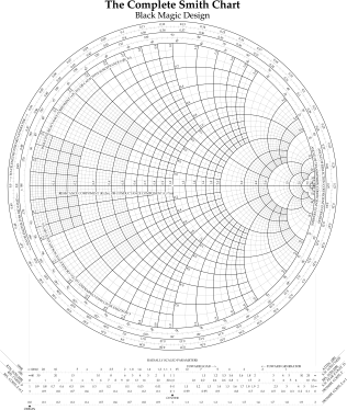
Show of hands: how many of you know how to use a Smith chart? :wink:

smithchart-thumb.png
[/quote]

Red marbles go first, green second. after 10 marbles each the one with the most marbles closest to the edge but not over the line wins. Simple...


er...


Oh dear. I don't think that's it now after all.

Shane
 
[quote author="NewYorkDave"]Show of hands: how many of you know how to use a Smith chart? :wink:[/quote]

<still shuddering> now that jst wasn't fair. At least give us a warning next time!

In all seriousness, I used to live and die by those things, working on coplanar waveguides for 5+GHz signals. Imagine how odd PCBs can be at the AF range. Now try and stuff a microwave signal through a piece of 1oz covered FR4 while keeping it skew and distortion free. I'm so glad I'm done with that.

RF is by no means voodoo. It operates under a very well defined set of rules. The problem is that those rules are usually obscure, often counterintuitive, and not taught in any substantive way in undergraduate courses. The books I've read do a very poor job of helping, putting the mysteries of RF engineering out fo the grasp of mere mortals (the majority of engineers). Bowick's book is the closest to recommendable I can find. You really owe it to yourself to pick up a copy atthe library :wink:

-dave
 
[quote author="PRR"]This is never really true. Resistors get goofy at MHz or GHz, and also vary a little with voltage and temperature. But the resistor makers try to do good. For most purposes, we may get by with pretending they are pure resistors. [/quote] I agree...there are many things we take for granted as only having resistance or that the impedance is constant...just not so!

In most cases, we don't care about the impedance except how low it goes...Some tweeters are tuned so high that they don't come near their DCR within their pass-band, but DCR is still a "safe" estimate of their load on the amp.
I would tend to "generically" agree with these statements, though they are rather broad.

The fact that the impedance rises to 100 ohms in a narrow band around 50Hz is not an issue.
Its obviously not an "issue"...its obviously resonance :green:

And proper crossovers will preserve this minimum load concept. (There are improper crossovers where a response-dip is "fixed" by a deep impedance dip to suck more power out of the poor amp.) A good 2-way or 3-way showing 6 ohms DCR can be connected as a 8 ohm load.
"Proper" or commercially viable or commercially available? One should never unknowingly assume this about any multi-way speaker system. The way that you or I would probably design one would be quite different from what is currently available on the market (depending on exactly which market we want to pinpoint). I have a set of Yamaha NS-6390 3-ways (that I bought as a sub for NS10..really midrangy). Their DCR measures about 6 Ohms, but I'll bet that the minimum impedance is 4 Ohms or less. Much of the time, I think crossover designers are designing not to smooth out dips but to minimize insertion loss. Why? Because people go for what is loudest in the showroom! When a system is designed this way, the minimum impedance is going to have a dip below the DCR that you would measure at the input terminals because of parallel impedances. I'm sure you realize this, PRR, just stating it for those who might not know already.

There are LOTS of speakers with "poorly" designed crossovers available. They do probably meet the design goals that the designers were tasked with, though!

Other that buying "bad" sounding speakers to mix with, I would probably never find a "consumer-grade" speaker that cost less than $1k that I would be happy to listen to. Most of it is just bad sounding to me. some of it is "okay", but just "okay".

HTH!
Charlie
 
[quote author="PRR"]
If the impedance turns out to be CONSTANT at all frequencies and voltages, we might call it a Resistance.
[/quote]
Not at all,
have hypothetical device (twopole) where
u=HT(i)
(voltage is hilbert transform of current)
This device have constant modulus impedance at every frequency
and it is not resistor.

xvlk
 
Back
Top