Bridge Type Comp/Limiter

GroupDIY Audio Forum

Help Support GroupDIY Audio Forum:

This site may earn a commission from merchant affiliate links, including eBay, Amazon, and others.

Michael A

Well-known member
Joined
Mar 9, 2006
Messages
67
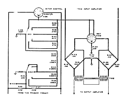
As an outgrowth of the magnetoresitive patent thread and the post by emrr citing the Collins 26W as an example of a bridge circuit limiter I've become intrigued by this architecture. I tried to model the idea a little bit in LTSpice and Tina, but I wasn't getting too far.

How does it sound? It seems like the 26W could be given a variable ratio, though it might be more of a problem than I foresee. Happens to use one of my favorite tubes too, the venerable 6N7. Transformers could be a problem of course.
1463652839_6169098f5f_o.jpg

Manual found herehttp://www.collinsradio.org/html/manuals.html

Michael
 
Transformers are a problem, in that one has to spend some serious $$ experimenting with available product, given that Collins doesn't own up to any real data on the critical piece. The 26C uses two identical hi-Z interstage coils to form it's bridge. The 26C (1937-41) stomps on most other tube limiters, and it has the crappiest frequency response you've ever seen. That's why one should forget the specs. It is almost impossible to make it pump with program material, and it can erase drum transients like hitting tape hard. Successful variable ratio may require a more complex sidechain amp, but no big deal.
 
I had hopes that an ultralinear output would do for the output, but I guess they are tapped at too low of an impedance. If I read the parts list right they want a 5k tapped at 3k. I'm not exactly sure how to take that, if they mean from end to end or if they mean a 5k coil, ie 10k end to end?

For the interstage what would the input impedance be? 15k? I was wondering if it even needs to be a single transformer or if you could use separate ones for each bridge. The dc current would be very small when the bridge was out of balance and it would be offsetting dc voltages when the bridge approached balance, so again little current in the transformer.

In any case it is sure a neat little design.

Michael
 
You can build any sort of circuit you want outside of the bridge portion.  Input and output are easy and a billion choices.   Do it SS if you want.   26C only says 690 henry's to two 490 henry windings, and measures like a 1:2.  In that circuit you need two of them.   My guess is 30K-50K range.  Couple hundred bucks for a pair of good quality high level iron; four or five hundred for stereo.  

They mean 5K total on the output.
 
What does the 26C circuit look like that it needs two interstages with split windings?

Since the 26W develops the sidechain voltage over a single resistor would varying the value of that resistor be enough to give variable ratios? It seems to me like that would do it, but I'm feeling particularly stupid tonight.

Michael
 
[quote author="Michael A"]What does the 26C circuit look like that it needs two interstages with split windings?

Michael[/quote]

take two split windings (4 coils) and connect them as one figure 8 arrangement. Four connections between four coils. Now put your variable resistances on the criss-crossed windings. Just another way to do a bridge.

Threshold and ratio are linked together with the bias voltage constantly applied to the 6H6 across R-147/148. The average level coming from the output transformer is critical to the chosen threshold/ratio. High ratio needs high drive level here. Notice they are tapping from the 3K points rather than the 5K points, which is a very slight voltage stepdown, a bit of isolation, and a bit of lowered sidechain drive impedance.

There's other discussions here about ways to separate the two functions with more complex sidechains.
 
Would you happen to know the dcr of the windings on either of these transformers?

Wouldn't threshold be determined by R147/148 and ratio by R152?

Michael
 
466 to 2500 split on the later 26C. 1100 to 1100 split on the earlier.

That resistor network is one and the same I believe. The two are not separately controled in this type of sidechain.
 
Yikes, they got 690H out of 1100R? My Lundahl 1660S only gets 290H out of 1250R.

I realize that neither threshold or ratio is a controllable parameter in the 26W. It seems, from looking that they could be controlled by varying R151 for the threshold and R152 for the ratio. I guess they would interact though.
Michael
 
I have iron for 26W - that is everything except the interstage.

What I do have for the interstage possibly is four 20kCT:20kCT interstage transformers. I was thinking of connecting 2 together in series for each side of the bridge to get the kind of impedance required.
This should work theoretically but I have no idea what the inductance is of my interstage transformers.
 
Seems reasonable to try it.  If the 20K is a split winding, one might do.    I don't know the inductance of the 26W type. 
 
Thank you emmr for detailed info
>>>
26C only says 690 henry's to two 490 henry windings, and measures like a 1:2.
 
Hmmm, never knew about the 26W...I was listening to and looking at the insides of this the other day:

http://www.masteringworks.com/shop-en/rockruepel-en/limit-one-limiter/

The circuitry was kind of confusing just looking at it. I didn't see any gain reduction element, unless it was hidden.  Circuitry looked pretty simple and there was a transformer that wasn't shielded and looked pretty custom in addition to two shielded transformers (three per side).  it also had your typical line driver chip on the output so those transformers were for something else. I bet its a bridge type limiter... Just with mini transformers and a solid state amp and sidechain.

It sounds good but does distort pretty quick. Its good on rock but on quiet stuff with forward vocals you'll hear it crackle. Worth pursuing though...
 
I'd rather not. I met the guy from the company not too long ago and I would feel weird posting it. I'm telling you, there's not much going on visually that would help you understand the Collins circuit better. Its literally 5 or so transistors, a couple op amps and the three transformers. Even with both channels the circuit board is half unused.

But I would recommend trying one out if you can, I think it is probably a good example of a modern interpretation of the Collins unit. You may not like it and it would save you a lot of work in building your own. Or you may really like it...I don't know.
 

Latest posts

Back
Top