DI input

GroupDIY Audio Forum

Help Support GroupDIY Audio Forum:

This site may earn a commission from merchant affiliate links, including eBay, Amazon, and others.

rafafredd

Well-known member
Joined
Jun 3, 2004
Messages
2,412
Location
Rio, Brazil
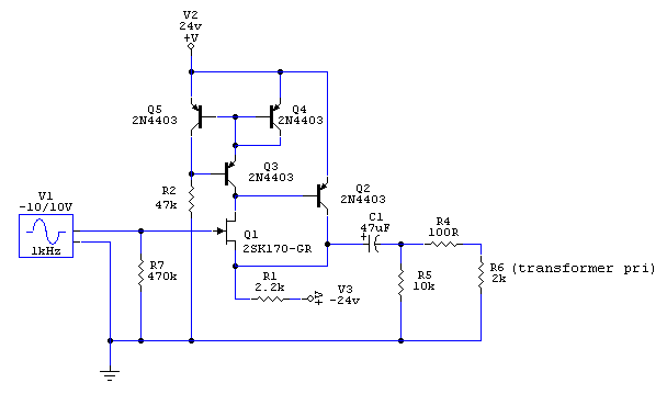
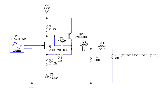
Idid this drawing of a very simple circuit for the DI input of my new four channels 990 preamps. Has anyone tried something like this with bipolar supply?

DI_input.gif


It must be simple and low parts count, to fit a very small space I have in the board for this. Just wondering if it would be worth breadboarding it as is or if anyone has any hints as I´m very new to discrete transistor stuff. Tubes are so much easier for my head... Can´t say why.
 
Since it's very much like the 'usual suspects' out there (the GR-circuit Dan K. made available, the two Jensen-circuits, etc) I guess it'll just work fine - the double supply shouldn't hurt, but might change sound w.r.t. the mentioned ones (I recall the GR-one was a bit 'strained' on purpose, this might change now) - but you always have the possibility to change values.

Why the double supply, since you have it available for the '990's anyway ? I expect just using +24V will have enough headroom for even the most potent signal coming from a passive bass (and for an active one you wouldn't need to go through this Hi-Z section).

Please keep us posted about what you find/hear,

Cheers,

Peter
 
I forgot, obviously Q1 wants to have some high valued resistor to ground and to be sure you'd want an AC-coupling cap as well (and that cap would like to have another high valued resistor from its left plate to ground).
 
This thing has gain as shown, right? Not sure I would do this--don't you have ~60 dB of potential gain after it? Converting to unity gain at least saves one resistor (R3). I would increase C1 a bit if space permits.

Samuel
 
[quote author="Samuel Groner"]This thing has gain as shown, right? Not sure I would do this--don't you have ~60 dB of potential gain after it? Converting to unity gain at least saves one resistor (R3). I would increase C1 a bit if space permits.

Samuel[/quote]
I guess Rafa started from the Dan K.-circuit and that one has a comparable amount of gain IIRIC.
Indeed, lots of gain later on (the 'NV even up to 7 B I saw),
but who knows, maybe it was the result of tweaking to taste and
then it ended up being like this ?

If this is about toying around oneself with this topology then tweak & try
(recommended :wink: ).
If it's about getting a quick & simple solder&forget circuit then I'd say just make it as the GR or Jensen examples & run at unipolar supply.


Bye,

Peter
 
If it's about getting a quick & simple solder & forget circuit then I'd say just make it as the GR or Jensen examples & run at unipolar supply.
Why--single supply makes it usually harder. The gate will often need some ~half supply bias which surely adds some parts.

Samuel
 
Thanks Raf, for offering up some food for thought. We see a lot of DI designs floating around, but a new design is a great starting point for comparison and analysis.

I would agree about not needing any voltage gain. The CountryHick, which I've been loving since I built one, drops some signal voltage in a step down transformer. That of course has the benefit of stepping up current and reflecting an easier load to the DI.

Not being limited by phantom feed resistors, I wouldn't think you'd need to use the 'GR' suffix 2sk170. Even the part that Jensen used with phantom, 2N4393, looks equivalent in IDSS to the the BL version. Which makes me wonder why they used the 2N4393 when the current draw they specify suggests they would have to select parts for the low end of the IDSS spread.

JensenSchematic (PDF)
2N4393 Datasheet(PDF)


Maybe its just FET love, but I wonder if there's a P-Channel FET that would complete the (EDIT: err, I meant CFP, aka Sziklai) and preserve the output drive.

Here's a post from Joe Malone about his discrete FET DI which uses another topology:
[quote author="JLM Audio"]
Are these available yet? What are they going to cost and do they sound much different sonically to the original Active DI's? Good call on the new sockets, I think these will be a lot better than the old ones which were easy to mis thread if you put too much torque on them.
Yes we have kits in stock for $38AUD and they will be up on the web site by the time we start back in mid January. We will also keep making IC DI kits as well. The real reason for the redesign was the difficulty in getting 1000 x OPA2604AP with less than a 20 week wait as I mentioned to Rochey at AES. But I thought I would try to solve the socket issue at the same time. We already use Cliff S4 sockets by the 1000s for our patchbays and they have been very reliable over the years so they were the logical choice but requires a relay to do the switching since the S4 only has break contacts.

The New FET DI is a Whites Cathode Follower type circuit like the 12BH7 on the output of a LA2A but done with 2 Fets instead. It runs in 10mA of Class A and then Class A/B if more current is needed. The lower FET in this circuit is basically a constant current circuit with its input modulated so can run on 24v to 48v without any changes. The relay is a 24v 10mA type with a 2k7 resistor in series to run it from 48v so if using 24v the 2k7 needs to be changed to a wire link. The relay is normally on when no jack is inserted. The unity gain circuit has better THD than the OPA2604 at low signal to medium signal levels. Best tone description would be pure and smooth with more warmth and fatness the harder the input is driven as a 2nd Harmonic starts to appear. But in normal use I think most people would find it hard to tell the FET & IC DI's apart.[/quote]
 
Not being limited by phantom feed resistors, I wouldn't think you'd need to use the 'GR' suffix 2sk170. Even the part that Jensen used with phantom, 2N4393, looks equivalent in IDSS to the the BL version. Which makes me wonder why they used the 2N4393 when the current draw specified suggests they would have to select parts for the low end of the IDSS spread.
Idss and actual drain current do not need to be equal! With the Sziklai pair the drain current is given mostly by the drain resistor, almost completely independent from Idss.

Samuel
 
Thanks Samuel. I had a feeling it was not relevant in this discussion.

Is there any noise benefit to using a device designed for higher idle current? I'm speculating that Jensen had an ulterior motive for using the 2N4393, which could simply be that they just got a good deal on batch of them.

Any comments on Sziklai versus White CF topologies for this application?
 
Nice;
it is my favorite topology, both for DI and condenser mics.
In case of DI you may want to eliminate R3 and C2.
However, 48V is a bit out of specs for 2SK170, though...
 
Is there any noise benefit to using a device designed for higher idle current?
Higher Idss means lower noise, but I doubt the difference is significant. It means higher capacity (and higher CM "auto-modulation" distortion for high source impedances) as well, so this might be the reason for spec'ing low-Idss parts (2SK170GR).

Samuel
 
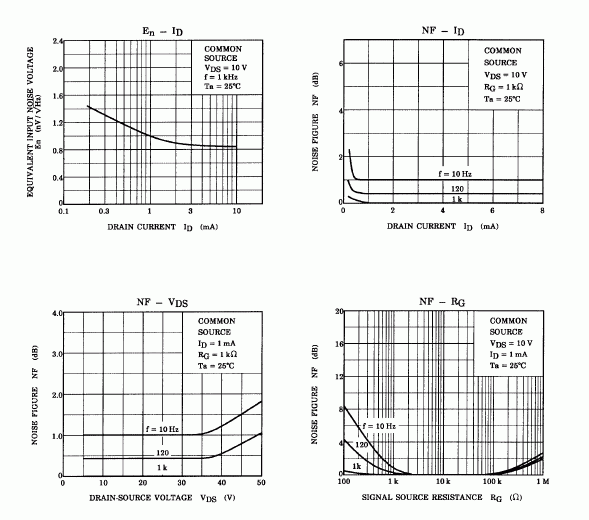
I would use up to +/18V rails, and decreased R1 down to 750 Ohm (at least 1 mA idle current is better than 0.3 mA according to specs, in terms of noise).

Also, I would decreased R2 as well for less distortions on a negative swing.

2sk170noise.gif
 
[quote author="Samuel Groner"]
If it's about getting a quick & simple solder & forget circuit then I'd say just make it as the GR or Jensen examples & run at unipolar supply.
Why--single supply makes it usually harder. The gate will often need some ~half supply bias which surely adds some parts.

Samuel[/quote]
That's true, a few more resistors which might be hard to fit.
But in case of going for the mentioned quick&solder&forget route, the Jensen & Great River circuits are 'proven' and the Great River is already meant for +24V, so no more thinking required; the component-picking can start right away while Rafa's soldering-iron heats up.
- While the drawn circuit at the top of the thread has less components (say 2 resistors less,... up to 3 less if you had taken the Great River-method for unipolar supply) but still requires some attention (like Wavebourn already said, the '170 & 48V)
 
Ok, in fact it looks a lot like jensen and GR, but I´ve started it based on this instead:

http://www.discovercircuits.com/PDF-FILES/NewPDF/FETbuffer1.pdf

Am I right to thik that the 170 in there will never see the full 48v? Well, now I´m worried. Also, would there be any need for the protection diodes at the input with this FET?

And now I´ve managed to loose a little parts (unity gain now) and add other for CCS. What do you guys think?

DI_input_ccs.gif


I think this last version still fits in my board layout... if there is any point in the CCS for such a simple thing.

(at least 1 mA idle current is better than 0.3 mA according to specs, in terms of noise).

Also, I would decreased R2 as well for less distortions on a negative swing.

Thanks for ideas... That´s what I´ll try next!
 
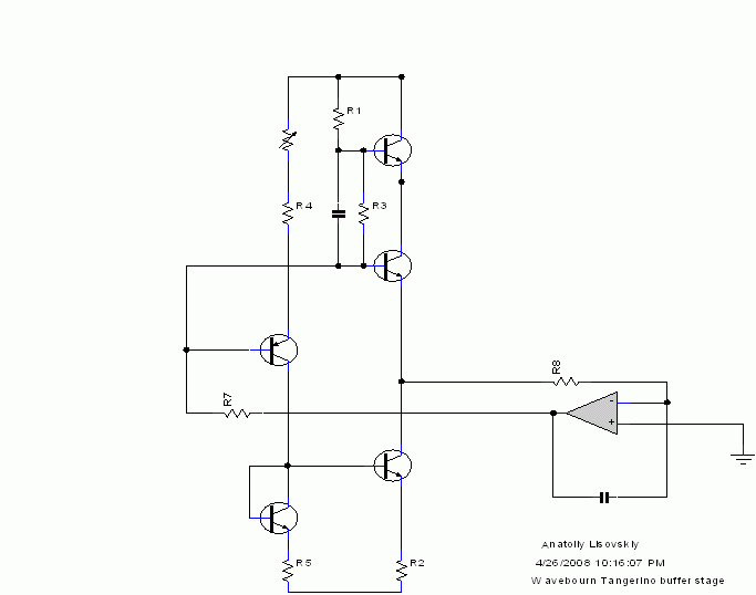
If you want to use 5 transistors I would go with a source follower loaded on a modulated CCS, bootstrapped by one more follower, so the main follower always sees nearly the same current and voltage for less distortions.

You may use JFETs for upper 3 transistors:

Tangerino.gif
 
Hay Anatoliy! Thanks for all your hints. I´m afraind I won´t be able to do much with what you posted. As I said, it´s my first time playing with discrete transistor stuff, and I would have to stare at the schem you posted for some hours, than find some answers on text books just to figure out all the parts values. I´ll try it later, cause I don´t think I can do it right away for this exact project, so I´ll keep going in the path I was going, with things I can understand right away. Also, this last schem I posted do have 5 transistors but they can be layed out very close to each other for a very compact space on my already flooded board. But really, thanks a lot for comming with new ideas, that´s what everybody wants here :thumb: I´m afraid I´m still too dumb to make anything with all you give me. :oops:

Well,

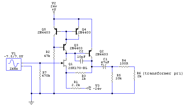
So, there is an advantage I see in making it NOT UNITY. Look:

DI_input_ccs_with_gain.gif


A few more components I´ll have to struggle on the board, but it makes Q2 collector sits at a higher voltage, and the output cap (that must be an electrolytic here) is always charged (or biased like some say) for better performance. Is my thinking right?

Also I´m still worried about the 40v FET thing. Pushing my rails down to +-18v would also be too much parts in this case, and it wouldn´t fit. I´m trying in fact to look for other low noise FETs that wold have a higher V rate. I know that sk30, sk147, sk117, sk363, sk364, sk369... I´ll take a look at datasheets.
 
Ok, it seems that there are some good 50v parts out there. I don´t know if as good as the sk170, but I know they are also regarded as very low noise at least in hifi audio forums and circles. I didn´t downloaded the pdfs, just looked for some ratings on goole.

so, 50v N-channel parts that might be handy:

sk117
sk118
sk163
sk363


sk373 is 100v!!! Don´t know about noise, but it says low-noise, and this, comming from toshiba... mmm

I´ll try to get the PDFs and study it.
 
[quote author="rafafredd"]
Am I right to thik that the 170 in there will never see the full 48v? Well, now I´m worried. Also, would there be any need for the protection diodes at the input with this FET?

And now I´ve managed to loose a little parts (unity gain now) and add other for CCS. What do you guys think?[/quote]

I think I would spend my parts a bit differently. For one thing, although loading Q2 with an I source does increase loop gain, the Wilson mirror has too much required voltage drop to work in that position, unless the Q2 emitter is biased a bit lower than +V. The other problem is the Wilson without any ballasting R's in the emitters of Q4 and Q5 is pretty noisy.

Then you will get better distortion performance with a current source in place of R1, or even a modulated one like Wavebourn shows in his post.

I wouldn't worry too much about breaking Q1 with overvoltage, although technically you could push it to a bit outside of ratings if you really blasted the input negatively. You could contrive a bootstrapped common-base stage or common-gate stage to shield Q1 from excessive volts.
 
[quote author="rafafredd"]Ok, it seems that there are some good 50v parts out there. I don´t know if as good as the sk170, but I know they are also regarded as very low noise at least in hifi audio forums and stuff. I didn´t downloaded the pdfs, just looked for some ratings on goole.

so, 50v N-channel parts that might be handy:

sk117
sk118
sk163
sk363


sk373 is 100v!!! Don´t know about noise, but it says low-noise, and this, comming from toshiba... mmm

I´ll try to get the PDFs and study it.[/quote]

Curves for 373 show 3dB noise figure at a kHz and 350 ohms source R. Since all of the noise is going to be series noise at that Z we can infer than e sub n is about 2.4nV per sq root Hz. Not bad, not as low as SK170 but likely lower than noise in most any source you're going to hook up to this.
 

Latest posts

Back
Top