DI input

GroupDIY Audio Forum

Help Support GroupDIY Audio Forum:

This site may earn a commission from merchant affiliate links, including eBay, Amazon, and others.
Hey Brad, I just got the parts you sent me today. I may even use these in this circuit here... Thanks for these.

As I said, I´ll have to take a look later at Wavebourn circuit to understand it. I can´t sight-read it.

On the other hand, I just aplyed some changes you´ve offered for my simpler circuit.

the Wilson mirror has too much required voltage drop to work in that position, unless the Q2 emitter is biased a bit lower than +V. The other problem is the Wilson without any ballasting R's in the emitters of Q4 and Q5 is pretty noisy.

Sounds bad, Wilson is out!

You could contrive a bootstrapped common-base stage or common-gate stage to shield Q1 from excessive volts.

More food for though.

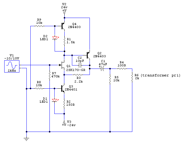
In the meanwhile, here are two more versions, with more comon CCS:
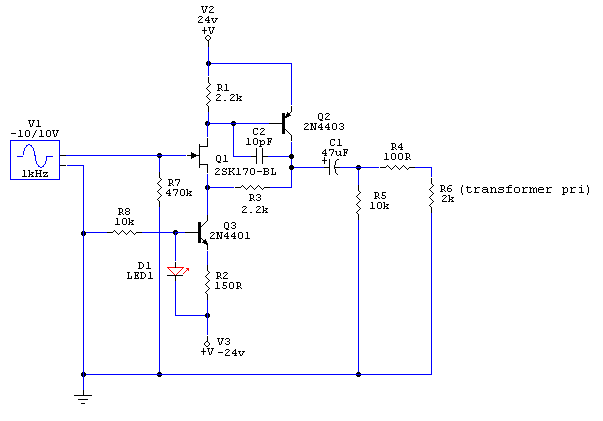
DI_input_ccs-1.gif


DI_input_dual_CCS.gif
 
Oh, man, how over-complicated can you make this?

You are worrying about the wrong things.

What are your requirements??? Jumping into a design before roughing-up some requirements is silly.

You won't get over 1V peak off the pickup.

You don't want even 1V peak into a Mike Input.

I'd argue that a guitar pickup was designed for a "hi-Z mike input", so to get into a low-Z mike input you want a LOSS of 5:1 or 10:1, the traditional voltage ratio of hi-Z to lo-Z.

Since max input is 1V, there's no reason you want 24V supply, much less your +/-24V= 48V supply. Doncha know the global is warming? 9V ought to be enough.

Low distortion is not a bonus in guitar amplification.

Extended bass response is not needed, nor wanted.

The pickup self-noise is a couple microVolts. You really want 34K in series with your first grid to cut AM radio reception in traditional funky unbalanced gitar cordery. So there is no point in exotic low-noise devices. Guitar pickups (and hi-Z mikes) evolved to give quite ample S/N with 12AX7. Any 10-cent JFET can do as well. And have lower input C than that large-area JFET.

If you can afford a 1:7 mike transformer, backward, one JFET is all you need. Cheaper is to add a BJT to get up to ~~3mA current.

2v2jmn5.gif
 
Jumping into a design before roughing-up some requirements is silly.

thanks PRR, for bringing me back to reality! The fact is that sometimes I get excited and the forum is a good place to learn from you guys with all the knowledge.

You won't get over 1V peak off the pickup.

Really, unfortunetly, with todays active basses it´s not really the case. Also, sometimes the musicians likes to put boosters and all kind of crap before the HiZ input of a preamp for a specific sound...

Since max input is 1V, there's no reason you want 24V supply, much less your +/-24V= 48V supply. Doncha know the global is warming? 9V ought to be enough.

I would love to use the rails I already have. It´s kind of impossible to squeaze another regulator in there... Since Brazilian energy is pretty "clean", because we have more rivers than anyone else in the world, energy that comes from the wall here is not directly guilty of global warming. We have hydroelectrics to spare energy for the next 20 years or so. Off coarse it has a impact on nature when they are beeing built thoght. Horrible impact!

Low distortion is not a bonus in guitar amplification.

mmm... That´s a very good point in there! Maybe that´s way DanK from GR strains the FET in very low current? (80uA?)

Extended bass response is not needed, nor wanted.

I´ve started with 10uF for ~-1dB at 20Hz. Then people said "go higher", and I´ve changed for 47uF... What do you think is a good response for bass guitars? maybe -1dB at 60Hz is enought? Well, it makes the use of higher quality film caps possible. Did I said I hate lytics?

Also, these are for my preamps using JE990 opamps, and 1:1 or 1:2 input transformers. So maybe even a little gain won´t hurt here. Input transformers are really beafy speced at 10-15dBm ones but goes as high as 20dBm for nice color. The circuit also has a impedance switch for 2k/8k impedance, by menas of series or parallel conneceted primaries. It´s the kind of amps that sometimes you mainly use for good transformer sound, and phantom power. But it´s clean enought for using ribbons at 66dB gain. It´s a take all preamp, without HAVING to relly on PAD.

Well, anyway, that series 33k resistor also means I should just use some of the thousands 2n5457 I have, and not worry for the hard to get and expensive japonese FETs, wich I should save for other projects like low noise input stage, not DI input... :shock:
 
Go with what PRR suggested except 3K resistor that is way too high for 2SK170 (it is noisier on currents below 1 mA -- see a curve I've posted before), for regulator you may use one more cheap JFET as a CCS and one Zener shunted by a capacitor.
Speaking of "No more than 1V", what happens when a musician inserting a jack touches ground by a tip? What happens in a dry weather, or on a high carpet in a studio? Definitely some input protection is desirable.

Speaking of my schemo, it consists of one emitter follower (source follower in case of FET); upper transistor (also an emitter follower) is a bootstrap device to keep voltage between collector and emitter less variable; lower transistor converts voltage variations to current variations; the lowest pair is a current mirror that reflects the variable current so current variations through the main follower are small. What happens with an emitter follower (or source follower) when voltage and current on it is nearly constant? Right, distortions are minimal.

This problem of variable current had been solved long time ago by White for vacuum tubes, but he used a feedback. I don't. Mikep also used a feedback, but for transistors (he converted my Tango to his Tangelo), if he chimes in and decides to share his thingy you may see what I mean.

Bootstrapped cathode follower was used long time ago by Tektronix in their oscilloscopes, AFAIR they bootstrapped it from output, while I took all signals from input (feed-forward approach) to eliminate transfer function fuzzing by feedbacks.

PS: for bass guitar go below 40 Hz; for modern multi-string-bass-mandolin go below 30 Hz.
 
di.jpg

This simple schematic works very well when used to drive a microphone pre :
- High input impedance > 1Mohm
- 20 dB input attenuation, needed with most instruments.
- 200 ohm balanced output to drive the micpre in normal condition.
 
> This simple schematic works very well when used to drive a microphone pre :

Very elegant though non-obvious. Thanks.

Hey, it even does the right thing if one (either) output is shorted to ground.

This one, as detailed, at higher supply voltages, does want a high Idss device like 2SK170.

> 3K resistor that is way too high for 2SK170

So don't use '170. It is a low-impedance device, also more expensive. You pay for low noise voltage, you get large gate capacitance and gate capacitance variation.... use the 10-cent JFET which I specified (your choice of actual part number).

> what happens when a musician inserting a jack touches ground by a tip? What happens in a dry weather, or on a high carpet in a studio?

JFET, not MOSFET. Junctions are moderately tough, not like thin oxide. YES you DO want some series resistance so fault current won't tend to infinity. And also for RF roll-off, which is not a problem 99% of the time but a real set-wrecker on the 1% bad days or bad location.

> I would love to use the rails I already have.

Share a rail with something else? Crosstalk? A 9V battery will last longer than the musicians. Probably longer than a set of good guitar strings.

> with todays active basses

Hell, those things can drive headphones directly, just jack into board line input. (Anyway they all use 9V batteries.....)

> my preamps using JE990 opamps, and 1:1 or 1:2 input transformers.

So take the transformer off. Deane would have a heart attack, git-tar straight into his precious child, but he's dead already. The noise performance is not "optimal", but not a problem. The pickup's DCR is ~~5K and probably a 990 won't get too much offset from that (it may match the feedback resistor). For non-pickup junk stuffed between, you may need a DC input return resistor, but "boosters and all kind of crap" can usually drive 10K load.

> as high as 20dBm for nice color.

12AX7 into a power pentode and cheap iron.... this aint string quartet.

Just giving an alternate opinion.
 
My (nonprofessional) advice would be to use cheap 2N3819 - works well - and:

c1 (470nF) is too big for an input cap imho, it will do funny thing to pickups.

I'd make a switch that would switch between:
10nF, 22nF, 47nF (for guitars) and
100nf (for basses)

R2 is on a high side imho - I suspect it will "suck tone" a bit, I usually lower the "standard" 10k serial resistors to a value near 2,2k (found that by experimentation, ymmv)

also, I'd make a switch for the R5 (not R1). I foud out that diff pickups react funny to values over 1Meg (this is also dependant on C1 value).

I'd switch: 1meg, 680k, 510k, 360k, 270k AND make the R1 of higher value, 4,7meg f.e.


now that would be a "mean machine" (imo).
 
[quote author="PRR"]You won't get over 1V peak off the pickup.[/quote]
I think it can be well above that, even for passive basses. But as we discussed a while ago the question is to which lengths we want to go to keep those transients undistorted:
http://www.groupdiy.com/index.php?topic=20976&postdays=0&postorder=asc&start=26

A link to that thread anyway, since it's quite the elder brother of this one:
http://www.groupdiy.com/index.php?topic=20976 (six pages)

[quote author="PRR"]You don't want even 1V peak into a Mike Input.[/quote]
Indeed, after buffering there should be attenuation.
Or skipping part of the subsequent chain; I do understand that for practical reasons most sources are routed thru mic-inputs, but if you have the choice why attenuate and bring it back up again ? (the '990-route won't be intended for 'colour' here I assume)

Bye,

Peter
 
[quote author="JPK"]
di.jpg

This simple schematic works very well when used to drive a microphone pre :[/quote]
Nice one, makes one think of a stripped Schoeps-type of condenser-mic circuit (but that not meant as a ahh, they got it from there).

So if just one active device is not enough you could add the two PNPs and phantom powering capability:
http://www.omnipressor.com/MicSchLib/Schoeps.pdf
(T1,T2,T3)

And if that is still not enough you could perhaps go for some more overkill:
condenser_mic_preamp.jpg


But why ? :cool:
For kicks could be a valid reason, so why not just build the simplest and the full-overkill and try both for a while.


Bye,

Peter
 
[quote author="JPK"]
di.jpg

This simple schematic works very well when used to drive a microphone pre :
- High input impedance > 1Mohm
- 20 dB input attenuation, needed with most instruments.
- 200 ohm balanced output to drive the micpre in normal condition.[/quote]

I like it. The best practical solution in this thread, if to mean connection to a mic input.
 
Or maybe for something different

Use a BJT Phase inverter for the fet but bootstrap the input bias string with a cap from the emitter and emitter resistor node to the bias resistors and a resistor of that node to the base.

I do like the FET circuit JPK posted
 
Old post....

skipwave said:
Here's a post from Joe Malone about his discrete FET DI which uses another topology:
[quote author="JLM Audio"]The New FET DI is a Whites Cathode Follower type circuit like the 12BH7 on the output of a LA2A but done with 2 Fets instead. It runs in 10mA of Class A and then Class A/B if more current is needed. The lower FET in this circuit is basically a constant current circuit with its input modulated so can run on 24v to 48v without any changes. The relay is a 24v 10mA type with a 2k7 resistor in series to run it from 48v so if using 24v the 2k7 needs to be changed to a wire link. The relay is normally on when no jack is inserted. The unity gain circuit has better THD than the OPA2604 at low signal to medium signal levels. Best tone description would be pure and smooth with more warmth and fatness the harder the input is driven as a 2nd Harmonic starts to appear.
[/quote]

This is the only place I found any info on the JLM FET DI, I haven't ever seen a schematic for it.  Anyway, I had a pair I'd built up for a project that didn't happen several years back, so I cut the 2K7 out to disable power to the relay, and wired them into some Hammond boxes to use as DI's with phantom power.  To get the phantom in, and not load everything down too much, I took a stab using a pair of 1K8's from XLR 2 and 3 to the 48V input on the cards, and it worked fine.  This gave right at 24V at the card, response measures great, and I can't reasonably overload it with pretty healthy line signals.  The pair of 1K8 are sort of "phantom build outs in reverse", taking the split phantom to the XLR and recombining it at the card, to maintain line balance throughout.  Additional buildout like this will reduce max current draw further, so you want to balance current with resistive loading.  In this case I took an educated guess, and it worked out fine.  If you were to leave the relay wired for power, current would be too great.    Here it wasn't needed, since there is no mic input looping through the card.    A quick jaunt through the calculator tells me with the 1K8's, the parallel resistive loading of the phantom network, when mated with a preamp having an actual (let's not get into that part) input Z of 1K5, converts to a system having a 980 ohm input Z for the FET DI to drive.  Smaller than 1K8 would let higher current pass, but lower the load to the FET even further. 
 
Back
Top