Help! How to calculate tube ( valve ) ouput impedance

GroupDIY Audio Forum

Help Support GroupDIY Audio Forum:

This site may earn a commission from merchant affiliate links, including eBay, Amazon, and others.

Buttercup

Well-known member
Joined
Jun 8, 2004
Messages
122
Location
Devon, England.
Hi

Does anybody have an accessible way to do this.
I have looked at data sheets but this information ( if it's there ) isn't obvious ( at least to me ).
Does it vary with Anode voltage/current?
Any help much appreciated.
Thanks.

Giles :grin:
 
It depends on the configuration. Generally speaking, for plate-out stages which are fairly common you can obtain the plate resistance from datasheets at given voltages (eg. 100V, 150V, 200V, etc.) and in this case the output impedance is this value in parallel with your chosen plate resistor.
 
For most triodes the data sheet assumes an a.c.-grounded cathode, and the plate impedance is listed as "plate resistance". If for some reason that is missing but mu and transconductance ("gm") are listed, the plate resistance is equal to mu/gm.

Note that plate resistance does not mean the resistive load in the plate circuit. It's the ratio of a small increment in plate voltage to the resulting small increment in plate current, at a given d.c. operating point, and assumes that the plate current is supplied from a very high impedance.

Plate resistance and gm vary with voltage and current, but at a fixed plate bias voltage their product, mu, is fairly constant for most triodes designed for use as linear amplifiers.
 
[quote author="Buttercup"]I have looked at data sheets but this information ( if it's there ) isn't obvious ( at least to me ).[/quote]

Hi Giles,
for an example for Brad's explanation of plate resistance, have a look at the graph at the bottom of page 5 ( http://frank.pocnet.net/sheets/010/e/ECC83.pdf ).

- Assume (as an example) an operation point with 175 V anode voltage and 1.7 mA current (which conveniently happens to be on the -1 V grid voltage curve :wink: ).

- While staying on the curve, move a bit to the left and right (= change the plate voltage a little) and note how much the plate current changes. (If the curve is not as straight as in this example, draw a tangent to the curve through that point and uses this instead)

- If the plate voltage changes from 150 V to 200 V, the current changes from 1. 2mA to 2.25 mA, so for a 50 V change in voltage, current changes by 1.05 mA.

- The plate resistance in this point (175V, 1.7mA) is (200 V - 150 V) / (2.25 mA - 1.2 mA) = 50 V / 1.05 mA = 48k.

- That's all.

HTH,
Matthias
 
> How to calculate tube ( valve ) ouput impedance

Whatever you want it to be.

However there is a broad class of "good audio amplifiers". For reasonable tubes, for reasonable supply voltages, not using any obviously goofy values, Z(out) is 0.15 to 0.4 times your DC plate resistor, lower Z(out) on lower-Mu tubes.

Example 1: 12AX7 in Fender guitar amp, 100K plate load, bypassed 1.5K cathode bias, 300V supply. Z(out) is 39K, or close enough to rock-n-roll.

Example 2: 12AU7 with 100K plate load to 300V can NOT pass 3mA, nor zero mA, will (if happy) flow 1mA-1.5mA and sit at 200V-150V. Page 3 of GE 12AU7 (yay! Frank's is back!) shows plate resistance soaring past 20K at this point (not the short-form boast of 7K at huge current). 20K in plate and 100K resistor is 17K Z(out).

> This is a great topic to motivate/introduce differential calculus.

You might like Keuhnel's The Fender Bassman 5F6-A. Maybe you even know Cramer's Rule.

> And show how we shouldn't be scared of it

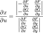
Who could be scared of this?
Now, by Cramer's rule, we see that:
0a7500b42abfae7ca487a02d7baebde9.png

This is now a formula in terms of two Jacobians:
a8ce1e23a6b313c8fae37a79a366090f.png

Similar formulae can be derived for
fc5f5eb7273b1ac643ec8257d39ac76d.png
,
2cb7387c0f56c58824879052f2b0a47f.png
,
b47dec30ca5ca2278e7f1250d52938d4.png
It gives exact answers to messy collections of formulas. But no simple formula describes a nonlinear tube "exactly", and no two tubes are alike. I followed Keuhnel with pencil and envelope and rough approximations, got "same +/-5%" answers when real tubes vary +/-20% and real tube-circuit results vary +/-10%... so why be exact?
 
> Does it vary with Anode voltage/current?

Yes, but practically very little.

GE 12AU7 shows RP laying pretty parallel for different plate voltages, but a wide range of RP as current changes.

But what current will we run? Usually as little as possible; clean hi-volt current is expensive. For a Voltage Amplifier, "ideally" we'd pick load very high and RP very low. But the world sucks, and stray capacitances give <1Meg impedances at the top of the audio band. Most volt-amp loads are 100K-500K, either resistors or 20KHz capacitances. So that limits us one way. The other way, we note low-Mu low-RP tubes, and high-Mu high-RP tubes, and gain is somewhat precious, so we can't pick an arbitrarily low RP.

So pick your load. Then pick your plate resistOR Rp 2 to 5 times higher so you get good pull-up drive. Then pick your tube for RP 2 to 5 times lower than Rp for good pull-down drive.

Unless the load is exceptionally high, a factor of "5" means an exceptionaly low RP tube, a low-Mu tube, and low gain. Factor of 2 or 3 is much more likely.

So Rp is likely to be OTOO 50K to 250K. Lower Rp means less gain and more costly current, a lose-lose solution. It can mean extended bandwidth, but the popular triodes are popular because you will usually get the full audio band with simple economical plans.

And RP is likely to be 2 or 3 times lower than Rp, 25K to 100K.

Back up. If the tube were exactly linear a certain way, a "good" bias might be to set the plate at half the supply rail. If that were true, the tube's linear plate resistance RP must be equal to the DC resistOR Rp. And then Z(out) must be RP||Rp or half of Rp.

So why do I say 0.15 to 0.4 times Rp?

Tubes are not linear. The plate curves, uh, curve. In a way which makes the small-signal resistance considerably smaller than the DC effective resistance: they start slow then steepen-up. So small-signal RP is less than DC operating point resistance, which is similar to DC load Rp. If we assume small-signal RP is half of DC RP, and load with Rp=RP, then we have (RP/2)||Rl, or 0.33 times Rl. A little higher when we work a high-Mu high-RP tube hard, a little lower when we work a low-Mu low-RP tube easy.

OTOH, if you are making a POWER amplifier, with say 2A3 at 250V 50mA, Z(out) is sheet-value RP for most practical purposes. And the "best load" for a triode Power Amp is around 2*RP, although wide deviations make small differences.
 
Wow, what a brilliant and hugely helpful set of answers!

I was really put off maths and formulae at school but I can quitely practise all this in my own time until I understand it a bit better and ( hopefully ) be able to put it to practical use.

Also, tube data sheets are starting to make a little more sense now.

Thanks!
 
> the small-signal resistance considerably smaller than the DC effective resistance

I wanted to check and ballpark this assertion. I pulled data for several triodes. I used the data-sheet "boast" conditions, which are sometimes far off where we'd run an Audio Voltage Amplifier; anybody is welcome to squint more typical values. I took Vp/Ip as "DC plate resistance RP" and the sheet value for dynamic plate impedance Rp.

12AX7
100V -- 0.5mA == 200K DC -- 80K dynamic == 0.4
250V -- 1.2mA == 208K DC -- 62K dynamic == 0.3

6SF5
100V -- 0.4mA == 250K DC -- 85K dynamic == 0.34
250V -- 0.9mA == 278K DC -- 66K dynamic == 0.24

12AT7
100V -- 3.7mA == 27K DC -- 15K dynamic == 0.55 (a)
250V -- 10mA == 25K DC -- 11K dynamic == 0.44

12AY7
250V -- 3mA == 83K DC -- 25K dynamic == 0.3

6AU6 as Triode
250V -- 12mA == 20.5K DC -- 7.5K dynamic == 0.37

6BQ7
150V -- 9mA == 16.6K DC -- 6.1K dynamic == 0.37

ECC88/6DJ7
90V -- 15mA == 6K DC -- 2.6K dynamic == 0.44 (a)

1D8 triode
45V -- 0.3mA == 150K DC -- 77K dynamic == 0.51
90V -- 1.1mA == 82K DC -- 44K dynamic == 0.5

12AU7
100V -- 12mA == 8.5K DC -- 6.5K dynamic == 0.76 (a)
250V -- 10mA == 25K DC -- 7.7K dynamic == 0.31

6L6 as Triode
250V -- 40mA == 6.3K DC -- 1.7K dynamic == 0.27

2A3
250V -- 60mA == 4.2K DC -- 0.8K dynamic == 0.19

6080
100V -- 100mA == 1K DC -- 0.31K dynamic == 0.31

(a) working near saturation

Casting-out the oddballs, mostly near-saturation or near-cutoff conditions, we see the Rp/RP ratio lays between 0.3 and 0.4 for most triodes.

RP matters because we load with a resistor Rl. With infinite load and perfect device, to get maximum voltage swing we set the DC idle point about halfway up B+. This is equivalent to saying that RP is made (by bias) equal to Rl. With real loads and tubes we may bias at 1/3rd to 2/3rd of B+, though tubes usually higher. So we are likely to bias the tube so its working RP is equal to 1 to 2 times Rl.

The audio output impedance is RP||Rl. What are the extremes?

RP=2*Rl, Rp=0.4*RP, (Rl)||(0.4*2*Rl) = 0.44*Rl
RP=1*Rl, Rp=0.3*RP, (Rl)||(0.3*1*Rl) = 0.23*Rl

In fact when you bias for higher RP, the ratio Rp/RP tends to drop. DC current falls faster than plate impedance. So you could round-in, say "0.3 to 0.4 times Rl", or even "0.35*Rl" or even "a third of the plate resistor", and be nearly right.

What use is this?

Why would you even care about Z(out)? Use the R-C Amp tables, find your load, take the suggested values, it will work good.

If you have a tone-network which needs <2K source to prevent unflatness, the approximation shows that no simple small happy triode is gonna do that. (6L6 will, while sucking 20 times more current than a typical tone control amplifier.)

If you have an RIAA network which starts with an ideal 100K series resistor, you might get by using a high Rp triode with a 300K Rl and no actual filter resistor. And it would be thrifty with current. But the available tubes must be biased-off pretty deep to run well this way, the Rp/RP ratio drops toward cutoff, so you might need to go 400K or 500K to get a 100K source impedance to your filter. And with different tubes it may be 80K or 120K, upsetting your RIAA response. Might be wiser to take the first 12AX7 condition, Z(out) about 57K, and add 43K of fixed-resistor to get to 100K. Now 20% changes in tube are only 13% changes in total Z(out), RIAA filter error is reduced.

If you don't bypass the cathode resistor, RP is unchanged but Rp increases, typically double. Now Z(out) is nearer 0.5 times Rl.

Cathode followers are, for any napkin-purpose, 1/Gm, or ~~1K for any small triode. Usually this is "very small" compared to tube-amp loads, Z(out) is "zero for practical purpose".

But note that Z(out) is NOT the load the amp can drive. Plate-loaded, it isn't too far off. Cathode loaded can't swing lower-Z loads than plate loaded.

In pentode voltage amps, Z(out) is 0.9*Rl for any practical purpose. Pentode Rp tends to be 5 to 20 times any practical DC-feed resistor we might use, so Rl dominates.

In pentode poweramps, Z(out) is 5 to 20 times the best-power load impedance. If the pentode were "perfect" then Z(out) would be infinite; there's no major advantage to making a pentode that stiff and they design for Rp to be "much" higher than RP, factor near 10.
 
Maybe just measure it where you are operating the tube

Older thread

http://www.groupdiy.com/index.php?topic=18028&postdays=0&postorder=asc&highlight=plate&start=0

I was a bit grumpy in some of my posts in that thread and the B+ change might be too much, also I was thinking tube microphone operating points.
The 12ax7 value is wrong it was a bad tube. I think I will rebuild the simple tester. I built it the first time with parts I had on the bench.
 
> Maybe just measure it where you are operating the tube

What, "work"??? Only if I get a Research Grant, enough to rent a Research Assistant to heat coffee and stonewall my telephone. Would be a fine idea, except you need a grant to hire a grant-writer good-enough to get a grant.

Anyway, the experiment has been done, the data published. White-shirt geeks slaved in hot labs in Camden and Owensboro plotting tube curves. They are not 8-digit accurate, and don't cover extreme low current, but are good-enuff to tell you what you really need to know.

On a Triode Ip/Ep plot of several G1 biases, the slope of the lines IS the dynamic impedance at that point. You lay a rolling-ruler tangent to the line at the point of interest, roll it (keeping parallel) to 0,0, then read the Ep at some convenient Ip and you know your dynamic plate impedance. The fact that we don't have a curve through say 1.23mA at 234V is no problem: there are no surprises, all change is gentle, you read the nearest point(s) given and that will be very close.

I ran lines on 12AX7. There are limits to my statement that Z(out) will be near 0.2 to 0.4 your DC load resistor.

A triode is a feedback amplifier, and if you suck the gain out of it, you lose the low-Z property; conversely if you let the gain come out, the Z is relatively low. And since the DC food the triode needs comes through the DC resistor, a small resistor drop (relative to plate drop) starves the triode. Most "good audio amplifiers" will avoid these situations. If you find yourself stuck in one, and care what Z(out) really is, analysis or experiment is better than asking unspecific questions on crazy forums.

When we have 360V across the tube and 60V on the resistor, Z(out) may be 0.5 times the resistor. Triode goodness is starved.

When we pick a very low value resistor, say 25K on 12AX7, such that gain is 0.3 times tube's ideal gain, Z(out) could be as high as 0.7 times the DC load resistor. The gain and triode-goodness is sucked out.

I was curious about the reverse bend in the 12AX7's zero-bias curve. At say 35V and 0.85mA the dynamic plate resistance is 51K, higher than the equivalent DC resistance 35V/0.85mA= 41K. If we get there with 200V and 200K, Z(out) is low. If we get there with 77V and 50K resistor, Z(out) is 0.5 times the resistor. Of course at zero bias we get zero output unless we can pull grid current, and the lack of grid current is the best thing about a thermionic device. Backed-off for some swingin'-room, Z(out) falls.

160bue1.gif
 

Latest posts

Back
Top