[email protected]
Member
- Joined
- Jan 27, 2012
- Messages
- 8
Looks fantastic Dave !


Hi Dave,Happy Easter to you too.
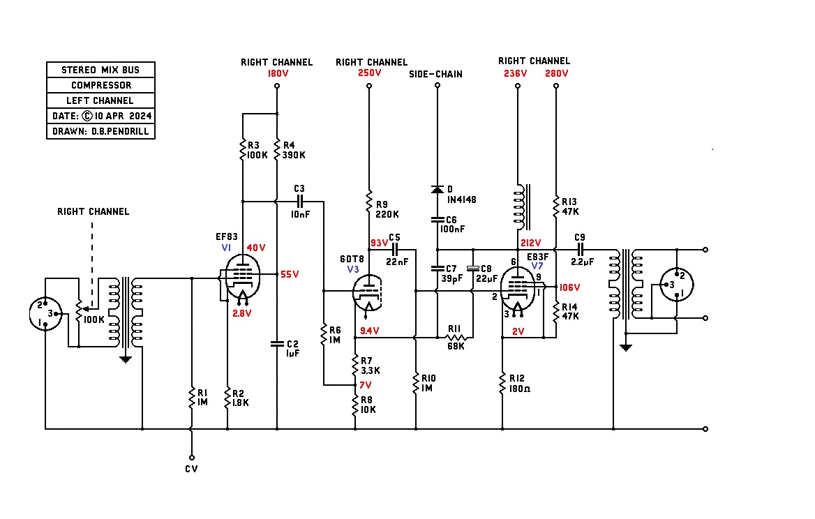
#1 Dual 100k lin pots.
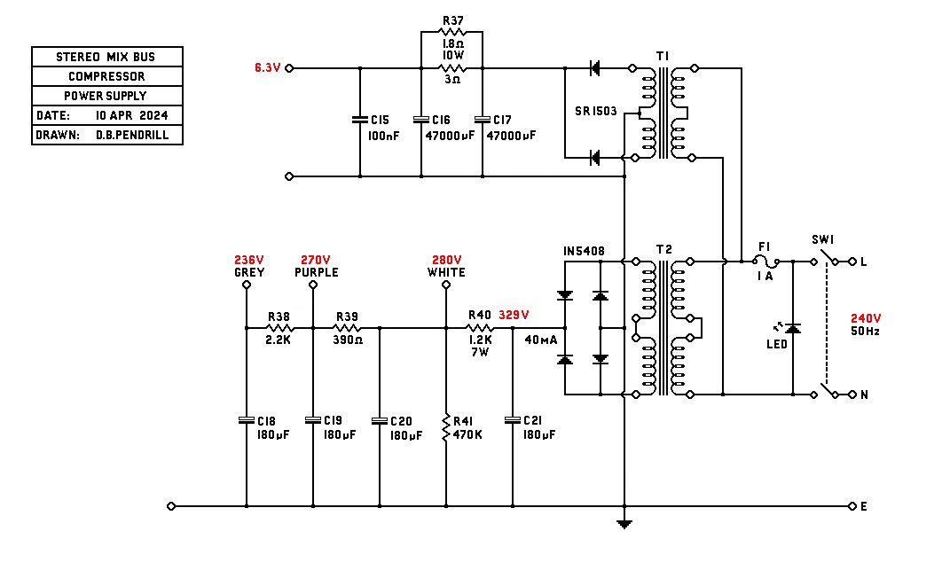
#2 B+ is a Triad VPT230-110 25VA from Farnell 1785731. Heater is a Multicomp 230-2x6V also from Farnell 1675043
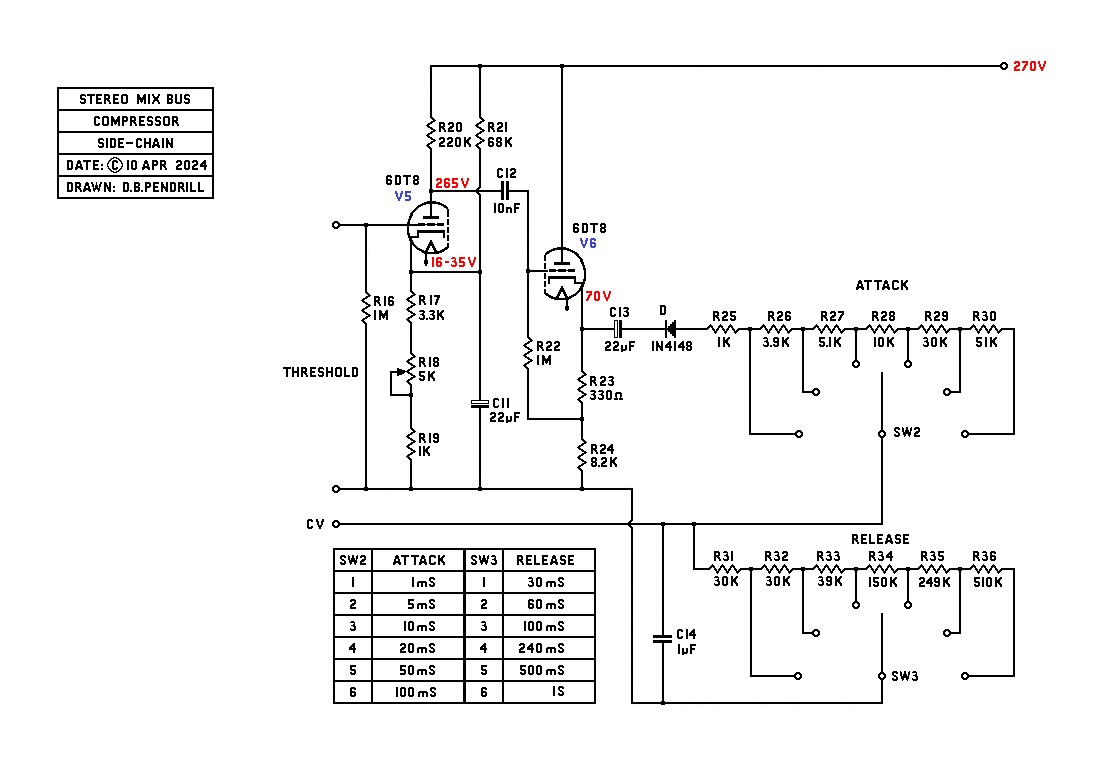
#3 Yes, but increasing the threshold will also switch off the side-chain.
#4 VU meters are fed from the output.
#5 No, the VU meters are set to a level, then the threshold reduced until say -3dB is achieved.
I use a switch for attack/release so that notes can be kept of the setting. Pots will be fine.
best
DaveP
Note to DIY'ers in countries with 120 volt mains. Use the Vigortronix VTX-146-015-206 part #99AC4549 instead of the Multicomp 230-2x6V.If you are enjoying what you do, maybe a part time apprentice would help and pass your legacy on to another generation.
Nice idea but I'm miles away from civilisation and have lots of other jobs to do as well. All the "from scratch" projects on this forum will have to be my legacy.If you are enjoying what you do, maybe a part time apprentice would help and pass your legacy on to another generation.
")
Fractionally OT, but our built in dishwasher died a few weeks ago. Our plumber came round to remove it and fit a new one. Apparently they are just held in by four screws at the front. The plumber undid these and started to pull out the dishwasher. It got about 6 inches then stuck. Nothing he did could make it move further. Then we looked at the work surface extension we had recently had fitted next to the dishwasher. Turned out the chippie used screws fix it to the existing work surface that were so long they went right through the woodwork and into the dishwasher. Doh!
Cheers
Ian